
Technical Product Specification


Functional Architecture Intel® Server Board S1400FP TPS
28 Intel order number G64246-003 Revision 2.0
3.2.3.1 Network Interface
Network connectivity is provided by means of one onboard Intel
®
Ethernet Controller I350
providing up to four 10/100/1000 Mb Ethernet ports. The NIC chip is supported by implementing
x2 PCIe Gen2 signals from the Intel
®
C600 PCH.
On the Intel
®
Server Board S1400FP, two for S1400FP2 and four for S1400FP4 external
10/100/1000 Mb RJ45 Ethernet ports are provided. Each Ethernet port drives two LEDs located
on each network interface connector. The LED at the right of the connector is the link/activity
LED and indicates network connection when on, and transmit/receive activity when blinking.
The LED at the left of the connector indicates link speed as defined in the following table:
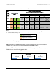
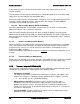
Table 6. External RJ45 NIC Port LED Definition
LED Color
LED State
NIC State
Green/Amber (Right)
Off
10 Mbps
Amber
100 Mbps
Green
1000 Mbps
Green (Left)
On
Active Connection
Blinking
Transmit/Receive activity
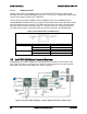
3.3
Intel
®
C602 (-A) Chipset Functional Overview
The following sub-sections will provide an overview of the key features and functions of the
Intel
®
C602 (-A) chipset used on the server board. For more comprehensive chipset specific
information, refer to the Intel
®
C600 Series chipset documents.
Figure 16. Functional Block Diagram – Chipset Supported Features and Functions