
Technical Product Specification


Functional Architecture Intel® Server Board S1400FP TPS
26 Intel order number G64246-003 Revision 2.0
of the counting registers. This prevents correctable error counts from building up over an
extended runtime.
The correctable memory error threshold value is a configurable option in the <F2> BIOS Setup
Utility, where you can configure it for 20/10/5/ALL/None.
Once a correctable memory error threshold is reached, the event is logged to the System Event
Log (SEL) and the appropriate memory slot fault LED is lit to indicate on which DIMM the
correctable error threshold crossing occurred.
3.2.2.6.2 Uncorrectable Memory ECC Error Handling
All multi-bit “detectable but not correctable“ memory errors are classified as Uncorrectable
Memory ECC Errors. This is generally a fatal error.
However, before returning control to the OS drivers through the Machine Check Exception
(MCE) or Non-Maskable Interrupt (NMI), the Uncorrectable Memory ECC Error is logged to the
SEL, the appropriate memory slot fault LED is lit, and the System Status LED state is changed
to solid Amber.
3.2.2.7 Demand Scrubbing for ECC Memory
Demand scrubbing is the ability to write corrected data back to the memory once a correctable
error is detected on a read transaction. This allows for correction of data in memory at detect,
and decrease the chances of a second error on the same address accumulating to cause a
multi-bit error (MBE) condition.
Demand Scrubbing is enabled/disabled (default is enabled) in the Memory Configuration screen
in Setup.
3.2.2.8 Patrol Scrubbing for ECC Memory
Patrol scrubs are intended to ensure that data with a correctable error does not remain in DRAM
long enough to stand a significant chance of further corruption to an uncorrectable stage.
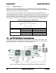
3.2.3
Processor Integrated I/O Module (IIO)
The processor’s integrated I/O module provides features traditionally supported through chipset
components. The integrated I/O module provides the following features:
PCI Express* Interfaces:
The integrated I/O module incorporates the PCI Express* interface and supports up to
24 lanes of PCI Express*. Following is the key attribute of the PCI Express* interface:
o Gen3 speeds at 8 GT/s (no 8b/10b encoding)
DMI2 Interface to the PCH: The platform requires an interface to the legacy
Southbridge (PCH) which provides basic, legacy functions required for the server
platform and operating systems. Since only one PCH is required and allowed for the
system, any sockets which do not connect to PCH would use this port as a standard x4
PCI Express* 2.0 interface.
Integrated IOAPIC: Provides support for PCI Express* devices implementing legacy
interrupt messages without interrupt sharing.