
Technical Product Specification


Intel® Server Board S1400FP TPS Functional Architecture
Revision 2.0 Intel order number G64246-003 25
Lockstep channels must be populated identically. That is, each DIMM in one channel must have
a corresponding DIMM of identical organization (number ranks, number banks, number rows,
number columns). DIMMs may be of different speed grades, but the iMC module will be
configured to operate all DIMMs according to the slowest parameters present by the Memory
Reference Code (MRC).
Performance in lockstep mode cannot be as high as with independent channels. The burst
length for DDR3 DIMMs is eight which is shared between two channels that are in lockstep
mode. Each channel of the pair provides 32 bytes to produce the 64-byte cache-line. DRAMs on
independent channels are configured to deliver a burst length of eight. The maximum read
bandwidth for a given Rank is half of peak. There is another drawback in using lockstep mode,
that is, higher power consumption since the total activation power is about twice of the
independent channel operation if comparing to same type of DIMMs.
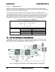
In Lockstep Channel Mode, each memory access is a 128-bit data access that spans Channel B
and Channel C. Lockstep Channel mode is the only RAS mode that allows SDDC for x8 devices.
Lockstep Channel Mode requires that Channel B and Channel C must be populated identically
with regards to size and organization. DIMM slot populations within a channel do not have to be
identical but the same DIMM slot location across Channel B and Channel C must be populated
the same.
3.2.2.5 Single Device Data Correction (SDDC)
SDDC – Single Device Data Correction is a technique by which data can be replaced by the
IMC from an entire x4 DRAM device which is failing, using a combination of CRC plus parity.
This is an automatic IMC driven hardware. It can be extended to x8 DRAM technology by
placing the system in Channel Lockstep Mode.
3.2.2.6 Error Correction Code (ECC) Memory
ECC uses “extra bits” – 64-bit data in a 72-bit DRAM array – to add an 8-bit calculated
“Hamming Code” to each 64 bits of data. This additional encoding enables the memory
controller to detect and report single or multiple bit errors when data is read, and to correct
single-bit errors.
3.2.2.6.1 Correctable Memory ECC Error Handling
A “Correctable ECC Error” is one in which a single-bit error in memory contents is detected and
corrected by use of the ECC Hamming Code included in the memory data. For a correctable
error, data integrity is preserved, but it may be a warning sign of a true failure to come. Note that
some correctable errors are expected to occur.
The system BIOS has logic to cope with the random factor in correctable ECC errors. Rather
than reporting every correctable error that occurs, the BIOS has a threshold and only logs a
correctable error when a threshold value is reached. Additional correctable errors that occur
after the threshold has been reached are disregarded. In addition, on the expectation the server
system may have extremely long operational runs without being rebooted, there is a “Leaky
Bucket” algorithm incorporated into the correctable error counting and comparing mechanism.
The “Leaky Bucket” algorithm reduces the correctable error count as a function of time – as the
system remains running for a certain amount of time, the correctable error count will “leak out”