
Technical Product Specification

Intel® Server Board S1400FP TPS Overview
Revision 2.0 Intel order number G64246-003 5
2.2.1
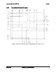
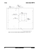
Server Board Connector and Component Layout
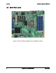
The following figure shows the layout of the server board. Each connector and major component
is identified by a number or letter, and a description is given in the figure below:
Figure 2. Intel
®
Server Board S1400FP Layout
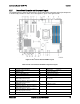
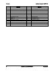
Table 2. Intel
®
Server Board S1400FP Component Layout
Description
Description
A
Serial B header
Y
TPM header
B
RMM4 header
Z
Storage Upgrade Key
C
Slot 2, 32bit/33MHz PCI
AA
BIOS Recovery jumper
D
eUSB SSD Header
AB
Password Clear jumper
E
Slot 3, PCI Express* Gen2 x4 electrical
with x8 physical connector
AC LCP header
F
Slot 4, PCI Express* Gen3 x4 electrical
with x8 physical connector
AD System Fan 1 header
G
RMM4 Lite header
AE
HSBP I
2
C header
H
Slot 5, PCI Express* Gen3 x8 electrical
with x8 physical connector
AF Chassis Intrusion header
I
Slot 6, PCI Express* Gen3 x8 electrical
with x16 physical connector
AG IPMB header
J
Status LED
AH
HDD LED header