
Technical Product Specification

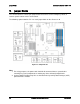

On-board Connector/Header Overview Intel® Server Board S1400FP TPS
Intel order number G64246-003 Revision 2.0
90
8.5
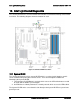
I/O Connectors
8.5.1
VGA Connector
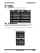
The following table details the pin-out definition of the VGA connector.
Table 39. VGA Connector Pin-out
Pin
Signal Name
Description
1
V_IO_R_CONN
Red (analog color signal R)
2
V_IO_G_CONN
Green (analog color signal G)
3
V_IO_B_CONN
Blue (analog color signal B)
4
TP_VID_CONN_B4
No connection
5
GND
Ground
6
GND
Ground
7
GND
Ground
8
GND
Ground
9
P5V
+5V DC
10
GND
Ground
11
TP_VID_CONN_B11
No connection
12
V_IO_DDCDAT
DDCDAT
13
V_IO_HSYNC_CONN
HSYNC (horizontal sync)
14
V_IO_VSYNC_CONN
VSYNC (vertical sync)
15
V_IO_DDCCLK
DDCCLK
8.5.2
SATA and SAS Connectors
The server board provides up to 6 SATA connectors: SATA-0, SATA-1, SATA-2, SATA-3,
SATA-4, SATA-5, and 8 SAS connectors: SATA/SAS-0, SATA/SAS-1, SATA/SAS-2,
SATA/SAS-3, SATA/SAS-4, SATA/SAS-5, SATA/SAS-6, and SATA/SAS-7.
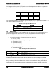
The pin configuration for each connector is identical and defined in the following table:
Table 40. SATA Connector Pin-out
Pin
Signal Name
1
GND
2
TXP
3
TXN
4
GND
5
RXN
6
RXP
7
GND
Table 41. SAS Connector Pin-out
Pin
Signal Name
1
GND
2
TXP
3
TXN
4
GND
5
RXN
6
RXP
7
GND