
Technical Product Specification

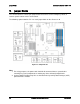

Intel® Server Board S1400FP TPS On-board Connector/Header Overview
Revision 2.0 Intel order number G64246-003
89
8.4.4
NMI Button Support
When the NMI button is pressed, it puts the server in a halt state and causes the BMC to issue
a non-maskable interrupt (NMI). This can be useful when performing diagnostics for a given
issue where a memory download is necessary to help determine the cause of the problem.
Once an NMI has been generated by the BMC, the BMC does not generate another NMI until
the system has been reset or powered down.
The following actions cause the BMC to generate an NMI pulse:
Receiving a Chassis Control command to pulse the diagnostic interrupt. This command
does not cause an event to be logged in the SEL.
Watchdog timer pre-timeout expiration with NMI/diagnostic interrupt pre-timeout action
enabled.
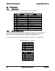
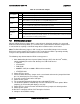
The following table describes behavior regarding NMI signal generation and event logging by
the BMC:
Table 38. NMI Signal Generation and Event Logging
Causal Event
NMI
Signal
Generation
Front Panel Diag Interrupt Sensor Event Logging
Support
Chassis control command (pulse diagnostic
interrupt)
X
–
Front panel diagnostic interrupt button pressed
X
X
Watchdog Timer pre-timeout expiration with
NMI/diagnostic interrupt action
X
X
8.4.5
NIC Activity LED Support
The Front Control Panel includes an activity LED indicator for each on-board Network Interface
Controller (NIC). When a network link is detected, the LED will turn on solid. The LED will blink
once network activity occurs at a rate that is consistent with the amount of network activity that
is occurring.
8.4.6
Hard Drive Activity LED Support
The drive activity LED on the front panel indicates drive activity from the on-board hard disk
controllers. The server board also provides a header giving access to this LED for add-in
controllers.
8.4.7
System Status LED Support
The System Status LED is a bi-color (Green/Amber) indicator that shows the current health of
the server system. The system provides two locations for this feature; one is located on the
Front Control Panel, the other is located on the back edge of the server board, viewable from
the back of the system. Both LEDs are tied together and will show the same state. The System
Status LED states are driven by the on-board platform management sub-system.