
Technical Product Specification


On-board Connector/Header Overview Intel® Server Board S1400FP TPS
Intel order number G64246-003 Revision 2.0
88
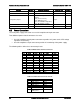
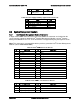
The following table provides the pin-out for this connector:
Table 36. Front Panel 30-pin Connector Pin-out
Pin
Signal
Pin
Signal
1
SB3.3V
2
SB3.3V
3
Key
4
SB5V
5
Power LED Cathode
6
System ID LED Cathode
7
3.3V
8
System Fault LED Anode
9
HDD Activity LED Cathode
10
System Fault LED Cathode
11
Power Switch
12
NIC#1 (1/2) Activity LED
13
GND (Power Switch)
14
NIC#1 (1/2) Link LED
15
Reset Switch
16
I2C SDA
17
GND (Reset/ID/NMI Switch)
18
I2C SCL
19
System ID Switch
20
Chassis Intrusion
21
Pull Down
22
NIC#2 Activity LED
23
NMI to CPU Switch
24
NIC#2 Link LED
25
26
27
NIC#3 Activity LED
28
NIC#4 Activity LED
29
NIC#3 Link LED
30
NIC#4 Link LED
8.4.1
Power/Sleep Button and LED Support
Pressing the Power button will toggle the system power on and off. This button also functions as
a sleep button if enabled by an ACPI compliant operating system. Pressing this button will send
a signal to the integrated BMC, which will power on or power off the system. The power LED is
a single color and is capable of supporting different indicator states as defined in the following
table:
Table 37. Power/Sleep LED Functional States
State
Power Mode
LED
Description
Power-off
Non-ACPI
Off
System power is off, and the BIOS has not initialized the chipset.
Power-on
Non-ACPI
On
System power is on
S5
ACPI
Off
Mechanical is off, and the operating system has not saved any context
to the hard disk.
S4
ACPI
Off
Mechanical is off. The operating system has saved context to the hard
disk.
S3-S1
ACPI
Slow blink
1
DC power is still on. The operating system has saved context and
gone into a level of low-power state.
S0
ACPI
Steady on
System and the operating system are up and running.
8.4.2
System ID Button and LED Support
Pressing the System ID Button will toggle both the ID LED on the front panel and the Blue ID
LED on the server board on and off. The System ID LED is used to identify the system for
maintenance when installed in a rack of similar server systems. The System ID LED can also be
toggled on and off remotely using the IPMI Chassis Identify command which will cause the LED
to blink for 15 seconds.
8.4.3
System Reset Button Support
When pressed, this button will reboot and re-initialize the system.