
Technical Product Specification


On-board Connector/Header Overview Intel® Server Board S1200V3RP TPS
Revision 1.3
78
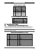
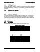
Pin
Signal Name
Pin
Signal Name
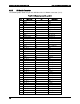
25
GND
26
TX_CLK
27
GND
28
RX_CLK
29
GND
30
PRESENT#
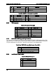
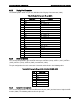
Table 30. Intel
®
RMM4 – Lite Connector Pin-out (J4B1)
Pin
Signal Name
Pin
Signal Name
1
3V3_AUX
2
SPI_RMM4_LITE_DI
3
KEY PIN
4
SPI_RMM4_LITE_CLK
5
SPI_RMM4_LITE_DO
6
GND
7
SPI_RMM4_LITE_CS_N
8
GND
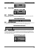
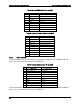
8.3.2 TPM connector
Table 31. TPM connector Pin-out (J8J1)
Pin
Signal Name
Pin
Signal Name
1
KEY PIN
2
LPC_LAD<1>
3
LPC_LAD<0>
4
GND
5
IRQ_SERIAL
6
LPC_FRAME_N
7
P3V3
8
GND
9
RST_IBMC_NIC_N
10
CLK_33M_TPM_CONN
11
LPC_LAD<3>
12
GND
13
GND
14
LPC_LAD<2>
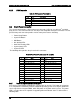
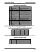
8.3.3 Intel
®
ESRT2 RAID Upgrade Key Connector
The server board provides one connector to support Intel
®
ESRT2 RAID Upgrade Key. The I
Upgrade Key is a small PCB board that enables RAID 5 software stack of ESRT2 SW RAID.
The pin configuration of connector is identical and defined in the following table:
Table 32. Intel
®
ESRT2 RAID Upgrade Key Connector Pin-out (J4A1)
Pin
Signal Name
1
GND
2
FM_PBG_DYN_SKU_KEY
3
GND
4
FM_SSB_SAS_SATA_RAID_KEY
8.3.4 Local Control Panel Header
Table 33. LCP Header Pin-out (J1G1)
Pin
Signal Name
1
SMB_SENSOR_3V3STBY_DATA
2
GND
3
SMB_SENSOR_3V3STBY_CLK
4
P3V3_AUX
5
FM_LCP_ENTER_N