
Service Guide


12 Intel® Server Board S1200BT Service Guide
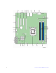
Figure 6. Configuration Jumpers Location
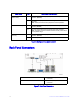
Back Panel Connectors
Figure 7. Back Panel Connectors
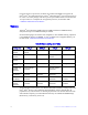
J1E2: Protected RTC
(CMOS clear)
1-2 These pins should have a jumper in place for normal system
operation. (Default)
2-3 If these pins are jumpered, the CMOS settings are cleared on the
next reset.
Note: These pins should not be jumpered for normal operation.
J1F3: BIOS Recovery 1-2 These pins should have a jumper in place for normal system
operation.(Default)
2-3 The main system BIOS will not boot with these pins jumpered.
Note: The system will boot from EFI-bootable recovery media with a
recovery BIOS image.
J1F2: ME Force
Recovery
1-2 These pins should have a jumper in place for normal system
operation. (Default)
2-3 ME force update model
Jumper Name Pins What happens at system reset…
A. Serial Port A C. NIC Port 1 (1 Gb) and Dual USB Port
Connector
B. Video D. NIC Port 2 (1 Gb) and Dual USB Port
Connector