
Technical Product Specification


350W Power Subsystem Intel® Server System R1304BTSSFAN/ R1304BTLSFAN/ R1304BTLSHBN TPS
4.2
Output Connectors
Listed or recognized component appliance wiring material (AVLV2), CN, rated min 80°C, 300
VDC should be used for all output wiring.
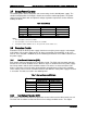
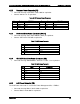
Table 14. 350W PSU Cable Lengths
From
Length
(mm)
To Connector #
Description
Power Supply cover exit hole
230
P1
Baseboard Power Connector
Power Supply cover exit hole
220
P2
Processor Power Connector
Power Supply cover exit hole
150
P3
AUX Power Connector
Power Supply cover exit hole
340
P7
2 x 4 HSBP Power Connector
P7
100
P5
SATA Drive Power Connector
P5
145
P4
SATA Drive Power Connector
Power Supply cover exit hole
600
P8
Mini SATA Drive Power Connector
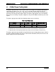
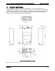
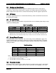
4.2.1
Baseboard Power Connector (P1)
Connector housing: 24-pin Molex* Mini-Fit Jr. 39-01-2200 or equivalent.
Contact: Molex* Mini-Fit, HCS, female, crimp 44476-1111 or equivalent approved by
Intel.
Table 15. P1 Main Power Connector
Pin
Signal
18 AWG Color
Pin
Signal
18 AWG Color
1*
+3.3VDC
Orange
11
+3.3VDC
Orange
3.3V S
Orange (24AWG)
12
-12VDC
Blue
2
+3.3VDC
Orange
13
GND
Black
3
GND
Black
14
PSON#
Green (24AWG)
4
+5VDC
Red
15*
GND
Black
5
GND
Black
COMRS
Black (24AWG)
6
+5VDC
Red
16
GND
Black
7
GND
Black
17
GND
Black
8
PWR OK
Gray
18
Reserved
N.C.
9
5 VSB
Purple
19
+5VDC
Red
10*
+12V
Yellow
20*
+5VDC
Red
12VRS
Yellow/White (24AWG)
5VRS
Red/White (24AWG)
Notes:
1. Remote Sense wire double-crimped.
2. P1 add cable bend requirement at P1.
Revision 2.4
18