
Service Guide


Intel
®
Server System R1304BTSSFAN/R1304BTLSFAN/R1304BTLSHBN Service Guide 53
6. If you need to add or replace a PCIe* Riser connector, see “Installing and
Removing a PCI Add-in Card” on page 56.
7. If you need to add or replace a PCI add-in card, see “Installing and Removing a PCI
Add-in Card” on page 56.
8. If you removed the PCIe* Riser assembly for another procedure, continue with that
procedure.
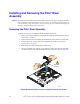
Installing the PCIe* Riser Assembly
Note: For clarity, the figures in this series of instructions does not show an attached add-in
card. If you are installing an add-in card, do so before installing the PCIe* riser assembly
into your server system.
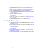
1. Lower the riser assembly into place over the add-in card slot. See letter “B” in
Figure 31.
2. Align the three hooks in the riser assembly with the matching slots at the back of
the server system. See letter “A” in Figure 31.
Figure 31. Installing PCIe* Riser Assembly into the Server System
3. Press down uniformly until the two hooks on the rear of the PCIe* riser assembly
engage the server system back panel slots. The riser cards will seat into the
matching sockets on the server board.
4. Connect any cables to add-in cards that require them. See your add-in card
documentation for information and add-in card requirements.
5. Install the server system cover. For instructions, see “Installing the Server System
Cover” on page 29.
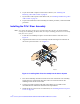
AF003695
PCI Riser
Socket
B
A
Riser Card
Connector