
Service Guide


50 Intel
®
Server System R1304BTSSFAN/R1304BTLSFAN/R1304BTLSHBN Service Guide
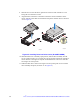
Figure 28. Attaching the latch to the Optical Drive
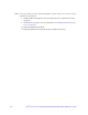
6. Pull the power and data cables through the front of the chassis opening.
7. Connect the mini SATA power connector on the optical drive.
8. Connect the data cable to the optical drive and to the SATA connector on the
server board.
9. Slide the optical drive assembly in, through the front of the chassis.
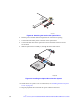
Figure 29. Installing the Optical Drive into the System
10. Install the server system cover. For instructions, see “Installing the Server System
Cover” on page 29.
11. Plug all peripheral devices and the AC power cable into the server.
AF003700
Rear View
of Optical
Drive
B
AF003702
Optical
Device Tray
Assembly