
Hardware User Guide


12Gb/s Intel® RAID Controllers User Guide 28
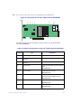
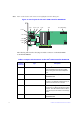
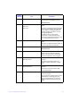
The following table describes the jumpers and the connectors on the Intel
®
RAID
Controller RS3DC080.
Table 5. Jumpers and Connectors on the Intel
®
RAID Controller RS3DC080
Jumper/
Connector
Type Description
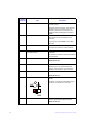
J1A2 3-pin connector IPMI-style I
2
C connector for Ports 4 to 7.
Supports SCSI Enclosure Services (SES)
over I
2
C through an internal I
2
C backplane
cable.
J1A3 20-pin connector Local RAID Maintenance Free Backup Units
connector.
Connects the RMFBU directly to the RAID
controller.
J1A4 3-pin connector IPMI-style I
2
C connector for Ports 0 to 3.
Supports SES over I
2
C through an internal I
2
C
backplane cable.
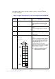
J1B1 2x8-pin header
Ports 0 to 3
Ports 4 to 7
Individual PHY and drive fault indication
header.
Connects to an LED that indicates whether a
drive is in a fault condition. One LED exists
per port. When lit, each LED indicates the
corresponding drive has failed or is in the
Unconfigured-Bad state.
The LEDs function in a direct-attach
configuration (no SAS expanders exist). Direct
attach is defined as a maximum of one drive
connected directly to each port.
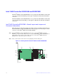
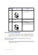
Note: The J5A1 connector on the Intel
®
RAID Controller RS3DC040 is a
single internal port connector.