
Hardware User Guide


12Gb/s Intel® RAID Controllers User Guide 32
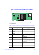
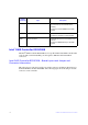
J1A9 4-pin connector On-board Serial Universal Asynchronous
Receiver/Transmitter (UART) connector.
Reserved for use.
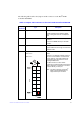
J1A10 2x8-pin header
Ports 0 to 3
Ports 4 to 7
Individual PHY and drive fault indication
header.
Connects to an LED that indicates whether a
drive is in a fault condition. One LED exists
per port. When lit, each LED indicates the
corresponding drive has failed or is in the
Unconfigured-Bad state.
The LEDs function in a direct-attach
configuration (no SAS expanders exist).
Direct attach is defined as a maximum of one
drive connected directly to each port.
J1A11 2-pin connector Global hard disk drive (HDD) activity LED
header.
Connects to an LED that indicates activity on
the drives connected to the controller.
J1A12 2-pin connector Test header.
Reserved for use.
J1B1 3-pin header Premium Feature Key header.
Enables support for selected advanced
features, such as Recovery, CacheCade*,
FastPath, and SafeStore* disk encryption.
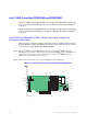
J1B2 x4 SAS Port 0 through Port 3
internal connector
One SFF-8644 mini-SAS HD-4e external
connector.
Connects the controller by cable to an
enclosure containing SAS drives or SATA
drives.
J2A1 x4 SAS Port 0 through Port 3
external connector
One SFF-8643 mini-SAS HD-4i internal
connector.
Connects the controller by cable to SAS
drives or SATA drives.
J2B4 Standard edge card connector The interface between the RAID controller
and the host system.
Along with the PCIe interface, this connector
provides power to the board and an I
2
C
interface connected to the I
2
C bus for the
Intelligent Platform Management Interface
(IPMI).
Jumper/
Connector
Type Description