2Gb/s Intel® RAID Controllers User Guide Intel Order Number: H21668-002
DISCLAIMER IINFORMATION IN THIS DOCUMENT IS PROVIDED IN CONNECTION WITH INTEL PRODUCTS. NO LICENSE, EXPRESS OR IMPLIED, BY ESTOPPEL OR OTHERWISE, TO ANY INTELLECTUAL PROPERTY RIGHTS IS GRANTED BY THIS DOCUMENT.
Preface This is the primary user guide for the 12Gb/s Intel® RAID Controllers. It contains installation instructions and specifications. Audience The people who benefit from this document are: • 12Gb/s Intel® RAID Controller users Organization This document includes the following chapters and glossary: • • Chapter 1 provides a general overview of the 12Gb/s Intel® RAID Controller. • • Chapter 3 describes the characteristics of the 12Gb/s Intel® RAID Controller.
Table of Contents Preface ........................................................................................................................iii Audience ...............................................................................................................................iii Organization ..........................................................................................................................iii Related Publication ...............................................................
23 12Gb/s Intel® RAID Controller Characteristics ...................................................... 25 12Gb/s Intel® RAID Controller Family .................................................................................25 Intel® RAID Controller RS3WC080 .............................................................................25 Intel® RAID Controller RS3DC040 and RS3DC080 ....................................................27 Intel® RAID Controller RS3MC044 .......................................
List of Figures Figure 1. Example of an Intel SAS Direct-Connect Application ................................................ 5 Figure 2. Example of an Intel SAS RAID Controller Configured with an LSISASx12 Expander 5 Figure 3. Example of the Intel® RAID Controller RS3DC080 Installation in a PCIe Slot ........ 17 Figure 4. Install the Barrel Standoff ........................................................................................ 19 Figure 5. Install the RAID Module .................................
List of Tables Table 1. 12Gb/s Intel® RAID Controller Features ..................................................................... 7 Table 2. 12Gb/s Intel® RAID Controller Array Limitations ......................................................... 9 Table 3. 12Gb/s Intel® RAID Controller Hardware Specifications ...........................................13 Table 4. Jumpers and Connectors on the Intel® RAID Controller RS3WC080 .......................26 Table 5.
1 12Gb/s Intel® RAID Controller Overview This document is the primary reference and user’s guide for the Intel® RAID Controllers based on the 12Gb/s SAS/SATA RAID-on-a-chip (ROC) devices. This document contains complete installation instructions and specifications for these RAID controllers. Overview The 12Gb/s Intel® RAID Controllers are high-performance intelligent PCIe-toSATA+SAS controllers with RAID control capability.
12Gb/s Intel® RAID Controllers with Support for RAID Maintenance Free Back Units The Intel® RAID Controllers RS3DC0x0, RS3SC008, RS3MC044, and RMS3CC080 support the RAID Maintenance Free Backup Unit that protects the integrity of the cached data on Intel® Integrated RAID Modules by offloading the data stored in the RAM cache to NAND flash during a power loss event. And it eliminates the need for lithium ion (Liion) batteries traditionally used to protect DRAM cache memory on RAID controllers.
The controllers support internal storage devices and external storage devices, which allow you to use a system that supports enterprise-class SAS drives and desktop-class SATA III drives. Each 12Gb/s Intel® RAID Controller can connect to drives directly and can use expanders to connect to additional drives. Simplified cabling between devices is an additional benefit. These devices are compliant with the Fusion-MPT™ architecture and provides a PCIe x8 interface.
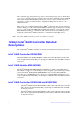
Intel® RAID Controller RS3MC044 The Intel® RAID Controller RS3MC044 is a PCIe 3.0 Serial-Attached SCSI/SATA Disk Array Controller that controls four internal SAS/SATA ports through one SFF-8643 miniSAS HD-4i internal connector and four external SAS/SATA ports through one SFF-8644 mini-SAS HD-4e external connector. Intel® RAID Controller RS3SC008 The Intel® RAID Controller RS3SC008 is a PCIe 3.
The following figure shows a direct-connect configuration. The Inter-IC (I2C) interface communicates with peripherals. The external memory bus provides a 32-bit memory bus, parity checking, and chip select signals for pipelined synchronous burst static random access memory (PSBRAM), nonvolatile static random access memory (NVSRAM), and Flash ROM. Figure 1.
The SAS interface uses the proven SCSI command set to ensure reliable data transfers, while providing the connectivity and flexibility of point-to-point serial data transfers. The serial transmission of SCSI commands eliminates clock-skew challenges. The SAS interface provides improved performance, simplified cabling, smaller connectors, lower pin count, and lower power requirements when compared to parallel SCSI.
The 12Gb/s Intel® RAID Controllers use Fusion-MPT architecture for all major operating systems, thinner drivers, and better performance. Summary of 12Gb/s Intel® RAID Controller Characteristics This section summarizes the features and benefits offered by the 12Gb/s Intel® RAID Controllers. It contains information on SAS features, SATA features, PCI performance, integration, usability, and flexibility. The 12Gb/s Intel® RAID Controllers have the following features. Table 1.
RS3WC080/ RMS3HC080 Feature Advanced array configuration and management utilities offer these capabilities: RS3DC040 RS3DC080/ RMS3CC080 RS3MC044 RS3SC008 Yes Yes Yes Yes Yes User-specified rebuild rate (specifying the percentage of system resources to use from 0 percent to 100 percent) Yes Yes Yes Yes Yes Nonvolatile random access memory (NVRAM) of 32 KB for storing RAID system configuration information; the MegaRAID SAS firmware is stored in flash ROM for easy upgrade.
Note: The number of devices varies depending on the Intel® RAID Controller product. Check the Intel website, http://www.intel.com, for specific details about your product. • They support wide ports that consist of two, three, or four PHYs within a single quad port. • • They support narrow ports consisting of a single PHY. They transfer data by using SCSI information units. SAS Array Limitations This section describes the array limitations of the 12Gb/s Intel® RAID Controllers.
These RAID controllers support 64-bit logical block addressing (LBA), which makes it possible to connect a large number of drives to the RAID controller, directly and through expanders. However, the actual number of drives that you can attach depends on the limits listed in this table rather than by actual RAID volume capacity.
• They support the internal SAS Sideband signal SFF-8485 (SGPIO) interface. Note: LED signals indicate an error condition or drive activity. The MegaRAID controllers support different blink patterns for these LEDs, depending on the user configuration and storage enclosure. For information about the LED blink patterns, contact your storage enclosure manufacturer.
6. Reconnect the power cords to the system. 7. Turn on the power to the system. The controller then detects the RAID configuration from the configuration data on the drives. Drive Migration Drive migration is the transfer of a set of drives in an existing configuration from one controller to another. The drives must remain on the same channel and must be reinstalled in the same order as in the original configuration. The controller to which you migrate the drives cannot have an existing configuration.
9. Reconnect the power cords to the system. 10. Turn on the power to the system. The controller detects the RAID configuration from the configuration data on the drives. Hardware Specifications You can install the 12Gb/s Intel® RAID Controllers in a computer with a motherboard that has a PCIe slot. The following table describes the hardware configuration features for the 12Gb/s Intel® RAID Controllers. Table 3.
Specification RS3WC080/RMS3HC080 RS3DC040/RS3DC080/RS3MC044/ RS3SC008/RMS3CC080 Multiple virtual drives per controller Up to 32 (this value is dependent on the firmware) Up to 64 (this value is dependent on the firmware) Online capacity expansion Yes Yes Dedicated and global hot spares Yes Yes Hot-swap devices supported Yes Yes Non-drive devices supported Yes Yes Mixed-capacity drives supported Yes Yes Hardware exclusive OR (XOR) assistance Yes Yes Direct I/O Yes Yes Architecture
2 12Gb/s Intel® RAID Controller Hardware Installation Requirements The following items are required to install a 12Gb/s Intel® RAID Controller: • • A 12Gb/s Intel® RAID Controller A host system with an available x8 PCIe 3.0 slot Note: These controllers also work in PCI Express first generation slots. The PCI Express software is backward compatible with previous revisions of the PCI bus and the PCI-X bus.
5. Perform a safety check. a. Make sure that all cables are attached correctly. b. Make sure that the RAID controller is installed correctly. c. Close the cabinet of the host system. 6. Reconnect the power cords to the system. 7. Turn on the power to the system. Make sure that the power is turned on to any external drives before the power is turned on to the host computer. If the computer is powered up before these devices, the devices might not be recognized.
4. Install the RAID controller. Select a PCIe slot, and align the controller’s PCIe bus connector to the slot, as shown in the following figure. Press down gently, but firmly, to make sure that the card is seated correctly in the slot. Secure the bracket to the computer chassis with the bracket screw. Note: This RAID controller is a PCIe x8 card, and it can operate in x8 or x16 slots.
5. Configure and install the SAS devices, the SATA devices, or both in the host computer case. Refer to the documentation for the devices for any pre-installation configuration requirements. 6. Connect the RAID controller to the devices. Use SAS cables to connect SAS devices, SATA devices, or both to the 12Gb/s Intel® RAID Controller. See SAS Device Cables and Connectors for SAS cable and connector information.
Detailed Installation for 12Gb/s Intel® RAID Modules This section provides detailed instructions on how to install your 12Gb/s Intel® RAID Module. The figures in this section show the installation of the Intel® RAID Module RMS3HC080 in the Mezzanine port. You can install the Intel® RAID Module RMS3CC080 in the same way. 1. Unpack the 12Gb/s Intel® RAID Module. Unpack and remove your RAID module. Inspect it for damage. If it appears damaged, contact your Intel Customer and Technical Support representative.
4. Review the RAID module jumpers and connectors. The jumpers are set at the factory, and you usually do not need to change them. See Chapter 3, 12Gb/s Intel® RAID Controller Characteristics, for diagrams of the 12Gb/s Intel® RAID Module that show their jumpers and connectors. 5. Install the RAID module. a. Attach the RAID module to the matching server board connector and press the module card firmly to engage the barrel standoffs. b.
The maximum cable length is 10 meters (393.37 in.). You can connect one device per SAS PHY unless you use an expander. System throughput problems can occur if the SAS cables are not the correct type. To minimize the potential for problems, use the following guidelines: — Use cables no longer than 10 meters (393.37 in.). (Use shorter cables, if possible.) — Use cables that meet the SAS specification. — Route the SAS cables carefully. 8. Turn on the power to the system.
SAS Device Cables and Connectors This section describes the cables and the connectors used on the 12Gb/s Intel® RAID Controllers and provides step-by-step instructions for connecting SAS drives, SATA drives, or both to the 12Gb/s Intel® RAID Controller. The SAS protocol and the SATA protocol use a thin, 7-wire connector instead of the 68-wire SCSI cable or the 40-wire ATA cable. Note: Use only straight SAS cables, not crossover SAS cables.
The following figure shows SAS connectors and SATA connectors on SAS drives and SATA drives, respectively. Cables connect internal connectors on the RAID controllers to connectors on SAS drives, SATA drives, or both. Both SAS drives and SATA drives can connect to SAS backplane receptacle connectors. The difference between the SAS connector and the SATA connector is the bridge between the SAS primary physical link and the power connector on the SAS controller, which the SATA connector does not have.
1. Insert the SFF-8643 internal mini-SAS HD-4i connector on the cable into a SFF8643 internal mini-SAS HD-4i connector on the Intel® RAID Controller RS3DC080, as shown in the following figure. 2. Plug the HDD connector on the other end of the cable into the connector on the SAS drive or SATA drive. 3. If you have another drive, connect it to another plug on the internal cable. You can connect other devices if the cable has more connectors. Figure 9.
3 12Gb/s Intel® RAID Controller Characteristics 12Gb/s Intel® RAID Controller Family The 12Gb/s Intel® RAID Controllers are dual-PHY, SAS PCI Express RAID controllers and are used in a system with a PCI Express slot. PCI Express goes beyond the PCI specification in that it is intended as a unifying I/O architecture for various systems: desktops, workstations, mobile devices, servers, communications, and embedded devices.
Note: Pin 1 on the headers and connectors is highlighted in red in this figure. Figure 10. Card Layout for the Intel® RAID Controller RS3WC080 J2 J4 J6 J3 J1B J1A J5 3_02070-00 EC1 The following table describes the jumpers and the connectors on the Intel® RAID Controller RS3WC080. Table 4.
Intel® RAID Controller RS3DC040 and RS3DC080 The Intel® RAID Controller RS3DC040 is a low-profile SAS+SATA RAID controller that controls four internal SAS/SATA ports through one SFF-8643 internal mini-SAS HD-4i connectors. The Intel® RAID Controller RS3DC080 is a low-profile SAS+SATA RAID controller that controls eight internal SAS/SATA ports through two SFF-8643 internal mini-SAS HD-4i connectors.
The following table describes the jumpers and the connectors on the Intel® RAID Controller RS3DC080. Table 5. Jumpers and Connectors on the Intel® RAID Controller RS3DC080 Jumper/ Connector J1A2 Type 3-pin connector Description IPMI-style I2C connector for Ports 4 to 7. Supports SCSI Enclosure Services (SES) over I2C through an internal I2C backplane cable. J1A3 20-pin connector Local RAID Maintenance Free Backup Units connector. Connects the RMFBU directly to the RAID controller.
Jumper/ Connector J2B4 Type Standard edge card connector Description The interface between the RAID controller and the host system. Along with the PCIe interface, this connector provides power to the board and an I2C interface connected to the I2C bus for the Intelligent Platform Management Interface (IPMI). J3L1 20-pin connector Remote RAID Maintenance Free Backup Units connector (on the backside of the controller). Connects the remote RMFBU to the RAID controller.
Jumper/ Connector J6B5 Type 2-pin connector Description Global drive fault LED header. Connects to an LED that indicates whether a drive is in a fault condition. J6B6 6-pin connector Complex programmable logic device (CPLD) header. Reserved for use. J6B7 2-pin connector Cache write pending header. Connector for an LED mounted on the system enclosure. The LED indicates that the data in the cache has yet to be written to the storage devices.
Note: Pin 1 on the headers and connectors is highlighted in red in this figure. Figure 12. Card Layout for the Intel® RAID Controller RS3MC044 J1A6 J1A11 J1A4 J1A9 J2L1 (Rear Side) J4A1 J1A12 J1A7 J2A1 J1A5 J1A10 J1A8 J6B1 J1B2 J1B1 3_02173-00 J2B4 The following table describes the jumpers and the connectors on the Intel® RAID Controller RS3MC044. Table 6.
Jumper/ Connector J1A9 Type 4-pin connector Description On-board Serial Universal Asynchronous Receiver/Transmitter (UART) connector. Reserved for use. J1A10 2x8-pin header Ports 0 to 3 Ports 4 to 7 Individual PHY and drive fault indication header. Connects to an LED that indicates whether a drive is in a fault condition. One LED exists per port. When lit, each LED indicates the corresponding drive has failed or is in the Unconfigured-Bad state.
Jumper/ Connector J2L1 Type 20-pin connector Description Remote RAID Maintenance Free Backup Units connector (on the backside of the controller). Connects the remote RMFBU to the RAID controller. J4A1 80-pin connector Flash Module DDR3 Interface. Connects the controller to a flash module. J6B1 20-pin connector Local RAID Maintenance Free Backup Units connector. Connects the RMFBU directly to the RAID controller.
Note: Pin 1 on the headers and connectors is highlighted in red in this figure. Figure 13. Card Layout for the Intel® RAID Controller RS3SC008 J1A5 J1A11 J1A6 J4A1 J1A8 J2L1 J1A12 J1B2 J6B1 J1B1 J1B4 3_02175-00 J1B3 J2B4 The following table describes the jumpers and the connectors on the Intel® RAID Controller RS3SC008. Table 7. Jumpers and Connectors on the Intel® RAID Controller RS3SC008 Jumper/ Connector J1A5 Type 2-pin connector Description Default Serial boot ROM (SBR) header.
Jumper/ Connector J1B1 Type 3-pin header Description Premium Feature Key header. Enables support for selected advanced features, such as Recovery, CacheCade*, FastPath, and SafeStore* disk encryption. J1B2 2-pin connector Cache write pending header. Connector for an LED mounted on the system enclosure. The LED indicates that the data in the cache has yet to be written to the storage devices. J1B3 2-pin connector Test header. Reserved for use.
Intel® RAID Module RMS3CC080 – Board Layout and Jumper and Connector Information This subsection provides the board layout, and the connector and jumper information for the Intel® RAID Module RMS3CC080. The following figure shows the jumpers and the connectors on the Intel® RAID Module RMS3CC080. Figure 14. Card Layout for the Intel® RAID Module RMS3CC080 J1 LSI SAS 3108 JT2 JT4 JT3 JT5 AF006553 The following table describes the jumpers and the connectors on the Intel® RAID Module RMS3CC080.
Jumper/ Connector Type Description JT4 4-pin connector On-board Serial Universal Asynchronous Receiver/Transmitter (UART) connector. JT5 3-pin header Premium Feature Key header. Enables support for selected advanced features, such as Recovery, CacheCade*, FastPath, and SafeStore* disk encryption.
Table 9. Jumpers and Connectors on the Intel® RAID Module RMS3HC080 Jumper/ Connector J1 Type 2-pin connector Description Test Header. Reserved for use. J4 4-pin connector On-board Serial Universal Asynchronous Receiver/Transmitter (UART) connector. J5 Dual x4 SAS Port 0 through Port 7 internal connector Two SFF-8643 mini-SAS HD-4i internal connectors. Connects the controller by cable to SAS drives or SATA drives.
Technical Specifications The design and implementation of the 12Gb/s Intel® RAID Controllers minimize electromagnetic emissions, susceptibility to radio frequency energy, and the effects of electrostatic discharge. The 12Gb/s Intel® RAID Controllers show the following marks and certifications: • • • • • • CE mark • • Japan VCCI C-Tick mark FCC Self-Certification logo Canadian Compliance Statement Korean MIC Taiwan BSMI CISPR Class B The following hardware is compliant with CSA C22.2 No.
RS3WC080, RMSHC080, RS3DC040, RS3DC080, RS3MC044, RS3SC008, and RMS3CC080 Specification • Card size • • • • • Array interface to the host PCI Express bus data transfer rate RS3WC080: Low-profile PCI Express adapter card size (68.90 mm x 152.35 mm) RMS3HC080: Mezzanine port PCI Express card size (64.39 mm x 128.98 mm) RS3DC0x0: Low-profile PCI Express adapter card size (68.90 mm x 167.65 mm) RS3MC044: Low-profile PCI Express adapter card size (68.90 mm x 167.
RS3WC080, RMSHC080, RS3DC040, RS3DC080, RS3MC044, RS3SC008, and RMS3CC080 Specification Maximum size of I/O requests 6.4 MB in 64-KB strips Maximum queue tags per drive As many as the drive can accept Strip sizes 8 KB, 16 KB, 32 KB, 64 KB, 128 KB, 256 KB, 512 KB, or 1 MB Maximum number of concurrent commands 255 Fault Tolerance The following table lists the fault tolerance features for the 12Gb/s Intel® RAID Controllers. Table 13.
Table 14. Power Supply for the Intel® RAID Controller RS3WC080 Power Mode Power Mode Description DC Power (Watts) Peak (on-max) Maximum 19.04 On-Normal/Typical Typical 13 Note: The charging circuitry for the battery pack on the optional BBU battery-backed daughter card uses +12V. If the BBU daughter card is mounted, the following power consumption figures apply: During trickle charging of the battery pack: Not applicable (no trickle charge for Li-ION).
Table 15. Power Supply for the Intel® RAID Controller RS3DC0x0 PCI Edge Connector State 1 State 2 3.3V supply 793 mA 793 mA +12V supply 915 mA 1090 mA 3.3V auxiliary supply 1 mA 1 mA Total Power 13.95 W 16.15 W Note: The charging circuitry for the battery pack on the optional BBU battery-backed daughter card uses +12V. If the BBU daughter card is mounted, the following power consumption figures apply: During trickle charging of the battery pack: Not applicable (no trickle charge for Li-ION).
The supply voltages are 12V ± 8 percent (from PCI edge connector only) and 3.3V ± 9 percent (from PCI edge connector only). The following table lists the power supply for the RAID controllers for these two states at the different voltages. Table 16. Power Supply for the Intel® RAID Controller RS3MC044 PCI Edge Connector State 1 State 2 3.3V supply 727mA 1030mA +12V supply 1050mA 1410mA 3.3V auxiliary supply 10mA 10mA Total Power 15.212W 20.
Table 17. Power Supply for the Intel® RAID Controller RS3SC008 PCI Edge Connector State 1 State 2 3.3V supply 800mA 880mA +12V supply 1000mA 1220mA 3.3V auxiliary supply 20mA 20mA Total Power 14.95W 17.91W Operating and Nonoperating Conditions for the Intel® RAID Controller RS3SC008 For the Intel® RAID Controller RS3SC008, the operating (thermal and atmospheric) conditions are as follows: • • Relative humidity range is 20 percent to 80 percent noncondensing.
Table 18. Power Supply for the Intel® RAID Module RMS3CC080 (TBD) PCI Edge Connector State 1 State 2 3.3V supply +12V supply 3.3V auxiliary supply Total Power Operating and Nonoperating Conditions for the IIntel® RAID Module RMS3CC080 For the Intel® RAID Module RMS3CC080, the operating (thermal and atmospheric) conditions are as follows: • • Relative humidity range is 20 percent to 80 percent noncondensing.
Operating and Nonoperating Conditions for the Intel® RAID Module RMS3HC080 For the Intel® RAID Module RMS3HC080, the operating (thermal and atmospheric) conditions are as follows: • • Relative humidity range is 5 percent to 90 percent noncondensing. • Temperature range: 0°C to +55°C Airflow must be at least 75 linear feet per minute (LFPM) to avoid operating the LSISAS3008 processor above the maximum ambient temperature.
Glossary B BIOS Acronym for Basic Input/Output System. Software that provides basic read/write capability. Usually kept as firmware (ROM-based). The system BIOS on the motherboard of a computer boots and controls the system. The BIOS on your host adapter acts as an extension of the system BIOS.
hot spare An idle, powered on, standby drive that is ready for immediate use in case of drive failure. A hot spare does not contain any user data. A hot spare can be dedicated to a single redundant array or it can be part of the global hot-spare pool for all arrays managed by the controller. When a drive fails, the controller firmware automatically replaces and rebuilds the data from the failed drive to the hot spare.
RAID levels A set of techniques applied to drive groups to deliver higher data availability, performance characteristics, or both to host environments. Each virtual drive must have a RAID level assigned to it. S SAS Acronym for Serial Attached SCSI. A serial, point-to-point, enterprise-level device interface that leverages the proven SCSI protocol set.