
Hardware User's Guide

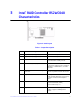
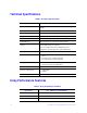
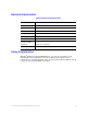

Table Of Contents
- Intel® RAID Controller RS2WC040 Hardware User’s Guide
- Preface
- Table of Contents
- List of Figures
- List of Tables
- 1 Overview
- 2 Intel® RAID Controller RS2WC040 Hardware Installation
- 3 Intel® RAID Controller RS2WC040 Characteristics
- Appendix A: Installation / Assembly Safety Instructions
- Appendix B: Drive Roaming and Drive Migration Install
- Appendix C: Regulatory and Certification Information
Intel® RAID Controller RS2WC040 Hardware User’s Guide 13
3 Intel
®
RAID Controller RS2WC040
Characteristics
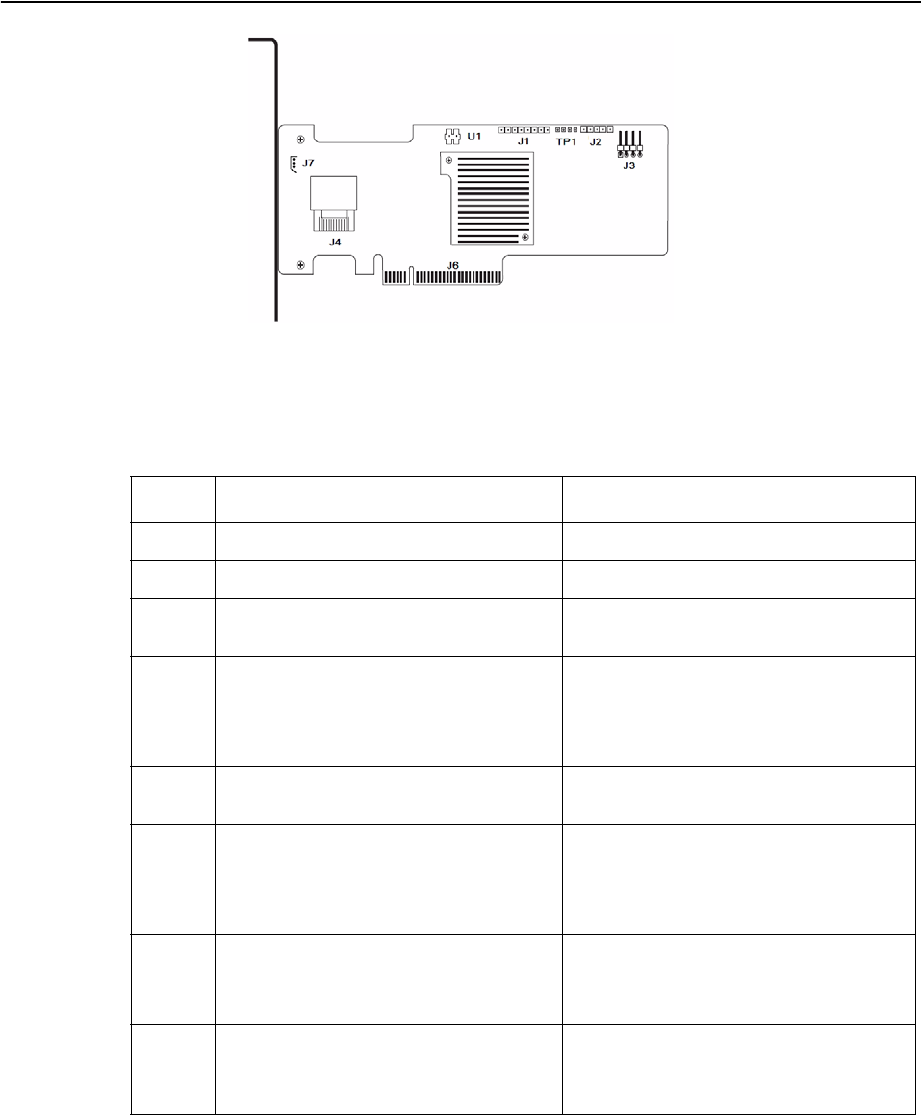
Figure 4. Card Layout
Table 1. Jumper Description
Jumper Type Description
J1 16-pin header (Not populated) Reserved for factory use
J2 10-pin header (Not populated) Reserved for factory use
J3 4-pin connector Connects to external, green or red LEDs
that indicate drive activity or faults.
J4 x4 Mini-SAS (SFF-8087) Ports 0–3 internal connector
Connects the cables from the controller to
SAS drives or SATA II drives, or a SAS
expander.
J6 PCI* Express Gen 2 x8 board edge
connector
x8 interface that provides connections on
both the top and the bottom of the board.
J7 3-pin connector PMI-style I2C connector
Supports SES (SCSI Enclosure Services)
over I2C over Internal I2C backplane
cable.
TP1 4-pin connector Universal Asynchronous
Receiver/Transmitter (UART)
Reserved for factory use
U1 2-pin connector RAID Premium Feature Key header.
Enables support for RAID premium
feature.