
Hardware User's Guide


Intel® RAID Controller RS2VB080/RS2VB040 Hardware User’s Guide 13
3 Intel
®
RAID Controller
RS2VB080/RS2VB040
Characteristics
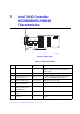
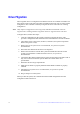
Figure 4. Card Layout
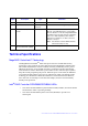
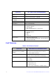
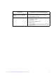
Table 1. Jumper Description
AF003649
JT1
Port
3-0
Port
7-4
JT2
JT3
JT6JT7
JT8
JT11
JT9
JT10
JT12
JT13
JT4
Jumper Description Type Comments
JT1 Dirty Cache LED Header 2-pin connector For connection to enclosure LED. When lit, it
indicates the data in the cache has not been
written to disk.
JT2 Drive Activity LED Header 2-pin connector LED signal for drive activity.
JT3 Board-to-board connector for
the memory board
20-pin connector Provides an interface to the memory board that
contains 512MB 800MHz DDR2 memory.
JT4 Drive Fault LED Header 2-pin connector LED signal for any drive fault.
JT6 Internal SAS/SATA Port
Connector, Ports 0-3
SFF8087 Connection to SAS/SATA devices.
JT7 Internal SAS/SATA Port
Connector, Ports 4-7 (for
RS2VB080 only).
SFF8087 Connection to SAS/SATA devices.
JT8 RAID Premium Feature Key
Header
2-pin connector Enables support for RAID Premium Feature.
JT9 Set Factory Defaults
Connector
2-pin connector Resets the board settings to the defaults set in the
factory.