
Hardware User's Guide


14 Intel® RAID Controller RS2VB080/RS2VB040 Hardware User’s Guide
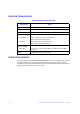
Technical Specifications
MegaRAID CacheVault™ Technology
LSI MegaRAID CacheVault
TM
flash cache protec-tion uses NAND flash memory
powered by a super-capacitor to protect data stored in the MegaRAID controller cache.
This module eliminates the need for a lithium ion battery traditionally used to protect
DRAM cache memory on PCI RAID controllers. The RAID controller automatically
writes the data in cache to flash when a power failure occurs, while the super-capacitor
keeps the current going during the process. When the power comes back, the DRAM is
recovered from flash and the system goes on without loss of data. The benefits of this
technology are elimination of hardware maintenance associated with LiON batteries,
lower total cost of ownership over the life of the adapter, and more environmentally
friendly cache protection.
Intel
®
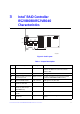
RAID Controller RS2VB080/RS2VB040 LEDs:
• One surface mounted GREEN system heartbeat LED (CRT3B1) to indicate that the
SAS2108 ROC ASIC is operating normally.
• One surface mounted RED system error LED (CRT3B2) to provide error
status signal.
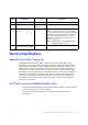
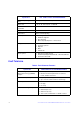
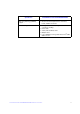
JT10 Debug Connector 2-pin connector Reserved.
JT11 Keyed I
2
C Connector 3-pin keyed
connector
Out-of-band enclosure management (SES2).
JT12 Individual Drive Fault LED
header
8 x 2 header Indicates drive faults. There is one LED per port.
When lit, each LED indicates the corresponding
drive has failed or is in the Unconfigured-Bad state.
The LEDs function in a direct-attach configuration
(there are no SAS expanders). Direct attach is
defined as a maximum of one drive connected
directly to each port.
Note: This header is used for RAID controllers
with internal SAS ports only.
JT13 Universal Asynchronous
Receiver/Transmitter (UART)
4-pin connector For factory and debug use.
Jumper Description Type Comments