
Intel RAID Controllers Interoperability Guide

DIY Storage System Guidance Using Intel® Server RAID Controllers Deployment Practices White Paper Set up the Storage Hardware System
Revision 1.0 7
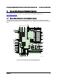
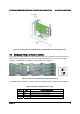
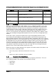
4.2 Board Front Panel Connector
The board provides a 24-pin SSI front panel connector (J1E4) for use with Intel
®
and third-party
chassis. The following table provides the pin-out for this connector.
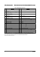
Table 4. Front Panel SSI Standard 24-pin Connector Pin-out (J1E4)
Pin Signal Name Description Pin
Signal Name Description
1 P3V3_STBY
(Power_LED_Anode)
Power LED + 2 P3V3_STBY Front Panel
Power
3 Key No
Connection
4 P5V_STBY (ID LED Anode) ID LED +
5 FP_PWR_LED_N Power LED - 6 FP_ID_LED_BUF_N ID LED -
7 P3V3
(HDD_ACTIVITY_Anode)
HDD Activity
LED +
8 FP_LED_STATUS_GREEN_N Status
LED
Green -
9 LED_HDD_ACTIVITY_N HDD Activity
LED -
10 FP_LED_STATUS_AMBER_N Status
LED
Amber -
11 FP_PWR_BTN_N Power
Button
12 NIC1_ACT_LED_N NIC 1
Activity
LED -
13 GND (Power Button GND) Power
Button
Ground
14 NIC1_LINK_LED_N NIC 1 Link
LED -
15 BMC_RST_BTN_N Reset Button 16 SMB_SENSOR_3V3STB_DATA SMB
Sensor
DATA
17 BND (Reset GND) Reset Button
Ground
18 SMB_SENSOR_3V3STB_CLK SMB
Sensor
Clock
19 FP_ID_BTN_N ID Button 20 FP_CHASSIS_INTRU Chassis
Intrusion
21 FM_SIO_TEMP_SENSOR Front Panel
Temperature
Sensor
22 NIC2_ACT_LED_N NIC 2
Activity
LED -
23 FP_NMI_BTN_N NMI Button 24 NIC2_LINK_LED_N NIC 2 Link
LED -
Note: The Front Panel Connector is identified by “NN” in Figure 2.