
Hardware User's Guide


Intel® RAID Controller RS2PI008 Hardware User’s Guide 11
3 Intel
®
RAID Controller RS2PI008
Characteristics
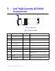
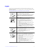
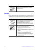
Figure 2. Card Layout
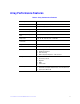
Table 1. Jumper Description
85040-00
J6B2
J6A1
J1A2
J1A1
J1A4
J1B1
J6B1
J1A3
Port
0-3
Port
4-7
J6A2
J6A3
Jumper Description Type Comments
J1A1 Universal Asynchronous
Receiver/Transmitter (UART)
4-pin connector For factory and debug use
J1A2 Test header 2-pin connector Reserved for factory use only
J1A3 Set Factory Defaults
Connector
2-pin connector Resets the board settings to the defaults set in the
factory
J1A4 External Mini SAS 4i
Connector, Ports 4-7
SFF8088 Connection to SAS/SATA devices
J1B1 External Mini SAS 4i
Connector, Ports 0-3
SFF8088 Connection to SAS/SATA devices
J6A1 Drive Fault LED Header 2-pin connector LED signal for any drive fault
J6A2 Drive Activity LED Header 2-pin connector LED signal for drive activity
J6A3 Dirty Cache LED Header 2-pin connector For connection to enclosure LED. When lit,
indicates the data in the cache has not been
written to disk
J6B1 Remote Battery Backup Unit
Connector
20-pin connector Provides an interface to the remote battery backup
unit
J6B2 Board-to-board Connector for
Battery Backup Unit
20-pin connector Provides an interface to the daughter card that
contains the battery backup unit.