
Technical Product Specification


Hardware Intel® RAID Controller RS2BL080 and RS2MB044 Technical Product Specification
Revision 2.1
Intel order number E64388-004
14
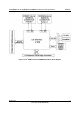
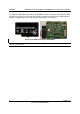
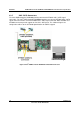
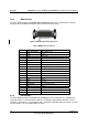
2.3.8 BBU Interface
The Intel
®
RAID Controller RS2BL080 and RS2MB044 boards can be attached to an external
backup battery unit (BBU) through the BBU board-to-board connector.
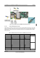
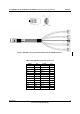
Figure 9 BBU Board-to-Board Connector
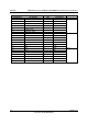
Table 3 BBU Connector Pin-out
Pin # Signal Description
1
VBB_DDR_MEM DDR/DDRII power
2 GND Ground
3 P12V +12V power
4 GND Ground
5
PFAIL_L Power fail
6
BBE Battery backup enabled
7
P1V8 1.8V power
8
BATT_PRSNT Battery present
9
P3V3_STBY 3.3V auxiliary power
10 GND Ground
11 GND Ground
12
P3V3 3.3V power
13 SCL I2C Clock
14 GND Ground
15 SDA I2C Data
16
BBSTATUS Battery backup status
17 GND Ground
18 BBSTROBE Battery Backup Strobe
19 GND Ground
20
VBB_DDR_MEM DDR/DDRII Power
2.3.9 PCI Interface
The Intel
®
RAID Controller RS2BL080 and RS2MB044 must be installed into a standard x8 or
larger PCI Express* slot that complies with the PCI Express Specification, Revision 2.0. The
controller is PCI Express* 1.0 compatible and is backward-compatible with x8 or larger slots that
are wired with x1, x2, and x4 PCI Express* lanes.