
Technical Product Specification


Hardware Intel® RAID Controller RS2BL080 and RS2MB044 Technical Product Specification
Revision 2.1
Intel order number E64388-004
16
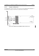
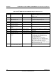
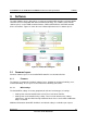
Table 4 Intel
®
RAID Controller RS2BL080 Jumpers and Connectors
Jumper Description Type Comments
JT1 Dirty Cache LED Header 2-pin connector For connection to enclosure LED. When lit,
indicates the data in the cache has not been
written to disk.
JT2 Drive Activity LED Header 2-pin connector LED signal for drive activity
JT3 Board-to-board Connector for
Battery Backup Unit
20-pin connector Provides an interface to the daughter card that
contains the battery backup unit.
JT4 Drive Fault LED Header 2-pin connector LED signal for any drive fault.
JT6 Internal SAS/SATA Port
Connector, Ports 0-3
SFF8087 Connection to SAS/SATA devices.
JT7 Internal SAS/SATA Port
Connector, Ports 4-7
SFF8087 Connection to SAS/SATA devices.
JT8 RAID Premium Feature Key
header
2-pin connector Enables support for RAID premium feature
JT9 Set Factory Defaults Connector 2-pin connector Resets the board settings to the defaults set in
the factory.
JT10 Debug Connector 2-pin connector Reserved
JT11 Keyed I
2
C Connector 3-pin keyed connector Out-of-band enclosure management (SES2)
JT12 Individual Drive Fault LED
header
8 x 2 header Indicates drive faults. There is one LED per
port. When lit, each LED indicates the
corresponding drive has failed or is in the
Unconfigured-Bad state.
The LEDs function in a direct-attach
configuration (there are no SAS expanders).
Direct attach is defined as a maximum of one
drive connected directly to each port.
Note: This header is used for RAID controllers
with internal SAS ports only.
JT13 Universal Asynchronous
Receiver/Transmitter (UART)
4-pin connector For factory and debug use.