
Intel RAID Controllers Interoperability Guide

Set up the Storage Hardware System DIY Storage System Guidance Using Intel® Server RAID Controllers Deployment Practices White Paper
Revision 1.0
8
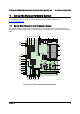
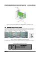
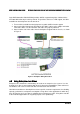
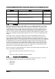
4.3 Connection between Chassis and Server Board
The connections from a Chenbro* chassis to the board are listed in the following table. The
letters under the server board column correspond to the letters identified in Figure 2 for the
server board and the pin numbers correspond to those defined in Table 4.
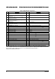
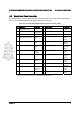
Table 5. Connection between Chassis and Server Board
Chassis Server Board Pin # (If needed)
Main power connector M
P12V4 connector H
Processor power connector Y
System FAN 1 X
System FAN 2 W
System FAN 3 U
System FAN 4 T
Front USB connector Z
Chassis intrusion connector RR
Power LED NN 1,5
HDD LED NN 7,9
Power SW NN 11,13
RESET NN 15,17
LAN 1 NN 12,14
Front Panel Connection
LAN 2 NN 22,24
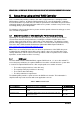
4.4 RAID Controller Installation
To install the RAID controller, follow these steps:
1. Power off the computer, all drives, enclosures, and system components. Remove the
power cord from the computer.
2. Remove the chassis cover and access the PCI Express* add-in card slots. See your
server chassis documentation for instructions.
3. Align the controller’s connector with a x8 or x16 PCI Express* slot on the server board.
4. Press down gently but firmly to ensure that the card is properly seated in the slot, as
shown in Figure 3. Secure the bracket to the computer chassis.