Intel® RAID High Available Solution Table of Contents Intel® RAID High Available Solution Best Practices White Paper Revision 1.0 October, 2013 Enterprise Platforms and Services Division - Marketing Revision 1.
Table of Contents Intel® RAID High Available Solution Revision History Date October, 2013 ii Revision Number 1.0 Modifications Initial release. Intel Confidential Revision 1.
Intel® RAID High Available Solution Table of Contents Disclaimers INFORMATION IN THIS DOCUMENT IS PROVIDED IN CONNECTION WITH INTEL PRODUCTS. NO LICENSE, EXPRESS OR IMPLIED, BY ESTOPPEL OR OTHERWISE, TO ANY INTELLECTUAL PROPERTY RIGHTS IS GRANTED BY THIS DOCUMENT.
Reference Documents Intel® RAID High Available Solution Table of Contents 1. 2. Introduction .......................................................................................................................... 7 1.1 Background...................................................................................................................... 7 1.2 Requirements and Configuration Diagram ...................................................................... 7 Installation ......................
Intel® RAID High Available Solution List of Figures List of Figures Figure 1. Two Server and JBOD Configuration Diagram .............................................................. 8 Figure 2. Enter the BIOS Boot Manager and EFI Shell ................................................................ 9 Figure 3. Install the Release Package ........................................................................................ 10 Figure 4. Install the RAID Controller HA Key ...............................
Reference Documents Intel® RAID High Available Solution < This page intentionally left blank. > 6 Intel Confidential Revision 1.
Intel® RAID High Available Solution List of Figures 1. Introduction 1.1 Background The Intel RAID High Availability (HA) Solution is designed for small-to-medium businesses, remote/branch offices or private cloud environments that need a high availability configuration of a server with local storage. This configuration of the Intel RAID HA solution provides two servers, two hardware RAID controllers and shared local storage with SAS disk drives.
Reference Documents Intel® RAID H High Available So olution Figure 1. Tw wo Server an nd JBOD Con nfiguration D Diagram 8 Inteel Confidential Revisiion 1.
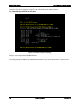
Intel® RAID High Available Solution List of Figures 2. Installation The installation process is detailed below. Some of these steps are performed using the server BIOS/UEFI utilities before the operating system is installed and some are performed after the operating system is installed and use operating system tools. Important note: Because a server cluster will be created, some of the steps require updates to be applied to one server, and then to the second server before proceeding to the following step.
Reference Documents Intel® RAID High Available Solution Using the EFI Shell, navigate (using the “cd” command) to the folder named: ir3_2208-HADAS_FWPKG-v23.6.0-0086 Figure 3. Install the Release Package Run the shell script named: UPDATE.NSH Once the package completes its download restart the server and repeat for the second server. 10 Intel Confidential Revision 1.
Intel® RAID High Available Solution 2.3 List of Figures Install and Update the HA RAID Controllers To install the RAID controller HA key, shut down the server, remove the power cords, open the lid and install the HA key onto the RAID controller. Figure 4. Install the RAID Controller HA Key Repeat this process for both servers. After each HA key has been installed on each of the RAID controllers in each of the servers, close the lid on the servers. Remove the USB flash drive containing the drivers.
Reference Documents 2.4 Intel® RAID High Available Solution Operating System Installation The operating system can be installed to drives connected to the raid controller, or to drives connected to the on server board ports.
Intel® RAID High Available Solution List of Figures Figure 6. Browse to the Driver After the drivers have been installed, the Windows installation will see the storage in the JBOD unit. A drive can be selected for the operating system, and the installation will proceed as normal. This process is repeated on the second server. Revision 1.
Reference Documents Intel® RAID High Available Solution After Windows Server has been installed on each server, the “Windows Standards-Based Storage Management” (SMI-S) feature needs to be installed. Figure 7. Install the SMI-S Feature 2.5 IP Addresses IP addresses need to be configured for the NICs in each server. Static IP addresses are recommended for the public LAN. Static IP addresses are required for the private LAN used for cluster communication. 14 Intel Confidential Revision 1.
Intel® RAID High Available Solution 2.6 List of Figures Failover Clustering Feature After the static IP addresses have been configured on both servers, the failover clustering feature can be enabled. Figure 8. Enable the Failover Clustering Feature At this point, verify that the RS25SB008 drivers are up to date. These drivers are located on the USB flash drive containing the drivers. Revision 1.
Reference Documents 2.7 Intel® RAID High Available Solution RAID Web Console 2 RAID Web Console 2 provides a way to manage the RAID volumes on the JBOD storage unit, including the creation of virtual drives (VD), RAID group configuration, and other related storage functions. It can be used to create one quorum disk and at least one volume that will be shared between the server cluster nodes. Additional volumes may be created as needed. Install the “RAID Web Console 2” (RWC2) onto each server.
Intel® RAID High Available Solution 2.8 List of Figures Registry Change to Enable Clustered RAID A registry change is required to enable support for Clustered Windows Servers using clustered RAID controllers. Edit the registry as described in the Microsoft Knowledge Base article: http://support.microsoft.com/kb/2839292. To add the key to the registry, follow these steps: 1. Open Registry editor (regedit.exe). 2.
Reference Documents 2.9 Intel® RAID High Available Solution Failover Cluster Manager After the reboot of both server nodes, start the Failover Cluster Manager on one of the server nodes. The first step is to validate the cluster configuration. The two nodes of the cluster need to be identified, and can be provided by entering their names directly or searching for them on the network. Figure 10. Failover Cluster Manager 18 Intel Confidential Revision 1.
Intel® RAID High Available Solution List of Figures First, the Validate Configuration wizard steps through the process of identifying the nodes that are participating in the cluster. After identifying the two nodes, a summary will be provided. Figure 11. Validate a Configuration Wizard – Select Servers or a Cluster Revision 1.
Reference Documents Intel® RAID High Available Solution After the nodes have been identified, the disks (volumes) that will participate in the cluster are tested. Figure 12. Validate a Configuration Wizard – Validating 20 Intel Confidential Revision 1.
Intel® RAID High Available Solution List of Figures After the disks have been tested, the wizard requests a name for the cluster. Figure 13. Create Cluster Wizard – Access Point for Administering the Cluster Revision 1.
Reference Documents Intel® RAID High Available Solution After the cluster name has been provided and the network addresses identified, the wizard provides a summary. Important note: In this example, the option to “add all eligible storage to the cluster” has been cleared (see image below), so that only specific volumes will be allocated to the cluster. This option is normally checked by default. Figure 14. Create Cluster Wizard – Confirmation 22 Intel Confidential Revision 1.
Intel® RAID High Available Solution List of Figures The wizard completes the creation of the cluster, with the exception of assigning disks to the cluster. Figure 15. Creation of Cluster Completed The process to assign disks to the cluster is initiated by selecting “Disks” on the left panel, then “Add Disk.” The available disks are presented and then displayed. In this example, we selected only two of the disks. Revision 1.
Reference Documents Intel® RAID High Available Solution Figure 16. Add Disks to a Cluster When complete, the cluster disks are available to the cluster. Figure 17. Cluster Disks Added In the Cluster Manager, select the cluster “MyCluster01” on the left panel, then select “More Actions” in the right panel and select “Configure Cluster Quorum Settings.” The wizard will step through the process of configuring the quorum witness.
Intel® RAID High Available Solution List of Figures Because this is the installation of the cluster, the quorum disk must be added, using the following selections: “Add or change the quorum witness” Followed by “Configure a disk witness” Figure 18. Configure Cluster Quorum When completed, the quorum disk witness is shown in the cluster storage. Figure 19. Quorum Disk Witness Shown Revision 1.
Reference Documents Intel® RAID High Available Solution The final step is to bring the clustered shared volume online to both nodes of the cluster, by selecting the disk and selecting “Add to Cluster Shared Volumes” on the right panel or by rightclicking on the mouse. Figure 20. Add to Cluster Shared Volumes The disks in the cluster should be changed from read-only to read-write in the disk management. The cluster is now operational.
Intel® RAID High Available Solution List of Figures Reference Documents R2312 Server* http://ark.intel.com/products/65399 RS25SB008 http://www.intel.com/content/www/us/en/servers/raid/raid-controllerrs25sb008.html AXXRPFKHA2 http://ark.intel.com/products/76542/Intel-RAID-Premium-Feature-KeyAXXRPFKHA2?q=Intel® RAID Premium Feature Key AXXRPFKHA2 JBOD2224S2DP http://www.intel.com/content/www/us/en/server-systems/storage-systemjbod2224s2dp-front-image.