
Intel RAID Controllers Interoperability Guide

Set up the Storage Hardware System DIY Storage System Guidance Using Intel® Server RAID Controllers Deployment Practices White Paper
Revision 1.0
6
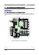
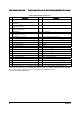
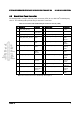
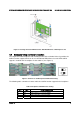
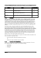
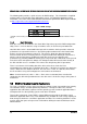
Table 3. Major Board Components
Description Description
A PCI-X 64-bit, 100-MHz full-length / full-height
slot 1
W System fan 2 header
B PCI-X 64-bit, 133-/100-MHz full-length / full-
height slot 2
X System fan 1 header
C
PCI Express* x4
[1]
or PCI express* x8
[2]
slot 3
(x8 physical connector)
Y Processor power connector
D PCI Express* x4 half-length / full-height slot 4
(x8 physical connector)
Z USB header
E CMOS battery AA IDE connector
F PCI Express* x16 full-length / full-height slot 6
(x16 physical connector)
BB
Enclosure management SATA SGPIO header
[2]
G CD-ROM line-in connector CC Intel
®
Local Control Panel header
H P12V4 connector DD Hot-swap backplane B header
I Back panel I/O ports EE
Enclosure management SAS SES I
2
C
[1]
J Diagnostic and Identify LEDs FF Hot-swap backplane A header
K System fan 6 header GG SATA 0
L System fan 5 header HH SATA 1
M Main power connector II
SATA 2 or SAS 0
[3]
N Auxilliary power signal connector JJ
SATA 3 or SAS 1
[3]
O DIMM sockets KK
SATA 4 or SAS 2
[3]
P Processor 1 socket LL
SATA 5 or SAS 3
[3]
Q Processor 2 socket MM USB port
R Processor 2 fan header NN Front control panel header
S Processor 1 fan header OO
SATA Software RAID 5 key connector
[2]
T System fan 4 header PP
SAS Software RAID 5 key connector
[1]
U System fan 3 header QQ Serial B / emergency management port header
V IPMB connector RR Chassis intrusion header
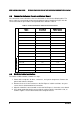
Note 1: Avaiable with product codes S5000XVNSAS/S5000XVNSASR or BB5000XVNSAS/BB5000XVNSASR.
Note 2: Available with product codes S5000XVNSATA/S5000XVNSATAR or BB5000XVNSATA/BB5000XVNSATAR.
Note 3: SAS connector available with product codes S5000XVNSAS/S5000XVNSASR or
BB5000XVNSAS/BB5000XVNSASR.