
Hardware User's Guide


Intel® RAID Controller RS25AB080 Hardware User’s Guide 27
Electrical Characteristics
All power is supplied to the adapter via the PCI Express 3.3V and 12V rail. Necessary
Voltages are provided by onboard switching regulator circuitry operating off of 12V and
3.3V rails.
The following states determine the typical current consumption of the board:
• State 1. During cache backup unit fast charge.
• State 2. During initialization of all RAID 5 logical drives simultaneously.
• State 3. While sitting idle at the DOS prompt.
— Supply voltage = 12V +/- 8% (from PCI edge connector only)
— Supply voltage = 3.3V +/- 9% (from PCI edge connector only)
— Actual power consumption.
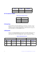
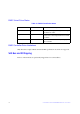
Table 11. Actual Power Consumption Table
Thermal and Atmospheric Characteristics
The maximum board temperature is limited by the LSI SAS2208 ROC Processor since it
uses the most power and will be the hottest component on the board.
• SAS2208 maximum junction temperature: 115
o
C
• Ambient temperature: maximum 60
o
C (without Super Cap 2 module)
• Maximum 45
o
C (with Super Cap 2 module)
• Airflow over SAS2208: 200 ft/min
• Environmental humidity: 20% to 80% non-condensing
• MTBF: greater than 300,000 hours
Safety Characteristics
The bare PC board shall meet or exceed the requirements of UL flammability rating V0.
The bare PC board shall also be marked with the supplier's name or trademark, type, and
UL flammability rating. The maximum electrical potential on the board will be 12.96V
potential difference, referenced from ground to +12V.
PCI Edge connector State1 State 2 State 3
3.3V supply 0.96A 0.86A 0.92A
+12V supply 0.81A 0.55A 0.56A
3.3V AUX. supply (cache backup unit appli-
cations only)
0.38A 0.2A 0.02A