
Hardware User's Guide


18 Intel® RAID Controller RS25AB080 Hardware User’s Guide
The drive failure tones repeat until the problem is corrected, or until the alarm is silenced
or disabled. The alarm can be silenced or disabled on the controller’s properties page in
the BIOS Console or by using the failed drive options pane in the Intel
®
RAID Web
Console 2.
Silencing the alarm is temporary. If the cause of failure still exists or if an additional
failure is detected, then the alarm sounds again when the system is rebooted. Disabling the
alarm is persistent across errors and reboots. When the alarm is disabled, a failure does not
cause it to sound until it is re-enabled.
The rebuild alarm tone functions differently. It remains ON during the rebuild. After the
rebuild completes, an alarm with a different tone sounds to signal that the rebuild is
complete. This is a one-time, non-repeating tone.
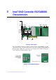
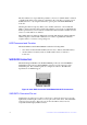
LED Placement and Function
The Intel
®
RAID Controller RS25AB080 contains the following LEDs:
• One surface-mounted heartbeat LED (Green Color) to indicate SAS2208 activity.
• Another surface-mounted system error LED (Amber Color) to indicate a
board error.
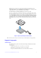
SAS/SATA Connectors
The Intel
®
Integrated RAID controller RS25AB080 provides two internal SFF8087
SAS/SATA signal connectors. Each SFF8087 connector provides support for four
SAS/SATA ports. The sideband signals are configured to adhere to the SFF-8485
Specifications for SGPIO support.
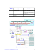
Figure 8. Intel
®
RAID Controller RS25AB080 SAS/SATA Connectors
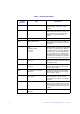
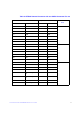
SAS/SATA Connector Pin-out
Signal names are with respect to the host; the device connected to the host reverses the
signal names. Transmit pins connect to receive pins on the other device. The SAS/SATA
connector is keyed at pin 1. These pin-outs for the serial ATA connector are not
compatible with the legacy PATA connector.
Internal connector