
Hardware User Guide

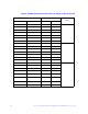
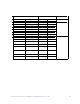
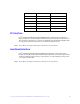

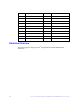

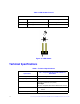
Table Of Contents
- Preface
- Table of Contents
- List of Figures
- List of Tables
- 1 Overview
- 2 Intel® Integrated RAID Module RMT3PB080 and RMT3CB080 Hardware Installation
- 3 Intel® Integrated RAID Module RMT3PB080 and RMT3CB080 Characteristics
- Appendix A: Drive Roaming and Drive Migration Install
- Appendix B: Installation/Assembly Safety Instructions
- Appendix C: Regulatory and Certification Information

24 Intel® Integrated RAID Module RMT3PB080 and RMT3CB080 Hardware User’s Guide
Note: The RAID controller in this document doesn't ship with SAS/SATA cables. Users can
separately order the SAS/SATA cable accessory kit as needed. Please see the Tested
Operating System List for available cable accessory kits at
http://www.intel.com/p/en_US/support/server/.
BBU/RMFBU Connector Pin-out
Table 4. BBU/RMFBU Connector Pin-out
Pin # Name Description
1 BBU_INPLACE1_N BBU plug-in confirmation 1
2 P12V 12V Power
3 P12V 12V Power
4 GND Ground
5 PWRGD_P1V5 1.5V VR power good
6 GND Ground
7 P3V3_AUX 3.3V auxiliary power
8 P1V5_BB 1.5V battery power
9 GND Ground
10 P3V3 3.3V power
11 P3V3 3.3V power
12 SMB_CLK_BBU_P3V3 Battery SMBus Clock
13 SMB_DAT_BBU_P3V3 Battery SMBus Data
14 BBU_STB_P3V3 3.3V auxiliary Battery
power
15 BBU_EN_P3V3 Battery Backup Enabled
16 BBU_PFAIL_N Battery Backup Power Fail
17 BBU_STATUS_P3V3 Battery Backup Status
18 RST_PF_PULSE_N Reset
19 FM_SCAP_FAULT Supper cap failure report
20 IRQ_HOST_PFAIL_N Host failure report
21 FM_PDOK_R_N Power Down OK to cache
module
22 USB2_P0_DP USB port0
23 USB2_P0_DN USB port0
24 USB2_P1_DP USB port1