
Hardware User Guide


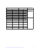
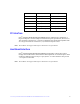


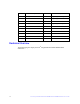

Table Of Contents
- Preface
- Table of Contents
- List of Figures
- List of Tables
- 1 Overview
- 2 Intel® Integrated RAID Module RMT3PB080 and RMT3CB080 Hardware Installation
- 3 Intel® Integrated RAID Module RMT3PB080 and RMT3CB080 Characteristics
- Appendix A: Drive Roaming and Drive Migration Install
- Appendix B: Installation/Assembly Safety Instructions
- Appendix C: Regulatory and Certification Information

Intel® Integrated RAID Module RMT3PB080 and RMT3CB080 Hardware User’s Guide 25
PCI Interface
Intel
®
Integrated RAID Module RMT3PB080 must be installed into a standard x8 or
larger PCI Express* slot that complies with the PCI Express Specification, Revision 3.0.
The controller is PCI Express* 1.0 and 2.0 compatible and is backward-compatible with
x8 or larger slots that are wired with x1, x2, and x4 PCI Express* lanes.
Note: The modules will support PCI Express* Revision 3.0 at post launch.
Host Board Interface
Intel
®
Integrated RAID Module RMT3CB080 board interface with the host system
through one custom board-to-board interface that implements one x8 PCI Express* lanes
signaling as defined in the PCI Express Specification 3.0. These interfaces also provide
+3.3 V power to the board.
Note: The modules will support PCI Express* Revision 3.0 at post launch.
25 USB2_P1_DN USB port1
26 P1V8 1.8V power
27 PWRGD_P1V8 1.8V power good
28 RST_MASK Reset mask
29 PWRGD_SYS System power good
30 BBU_INPLACE2_N BBU plug-in confirmation 2
Pin # Name Description