
Hardware User Guide


12Gb/s Intel® RAID Controllers User Guide 34
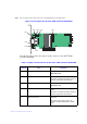
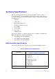
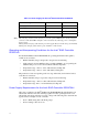
Note: Pin 1 on the headers and connectors is highlighted in red in this figure.
Figure 13. Card Layout for the Intel
®
RAID Controller RS3SC008
The following table describes the jumpers and the connectors on the Intel
®
RAID
Controller RS3SC008.
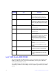
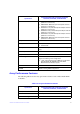
Table 7. Jumpers and Connectors on the Intel
®
RAID Controller RS3SC008
Jumper/
Connector
Type Description
J1A5 2-pin connector Default Serial boot ROM (SBR) header.
Reserved for use.
J1A6 2-pin connector Global drive fault LED header.
Connects to an LED that indicates activity on
the drives connected to the controller.
J1A8 5-pin connector CPLD header.
Reserved for use.
J1A11 2-pin connector Global hard disk drive (HDD) activity LED
header.
Connects to an LED that indicates activity on
the drives connected to the controller.
J1A12 x4 SAS Port 0 through Port 7
external connector
Two SFF-8644 mini-SAS HD-4e external
connectors.
Connects the controller by cable to an
enclosure containing SAS drives or SATA
drives.
3_02175-00
J1A11 J4A1
J2L1
J6B1
J1A5
J1B4
J1B3
J2B4
J1B2
J1B1
J1A8
J1A6
J1A12