
Hardware User Guide


31 12Gb/s Intel® RAID Controllers User Guide
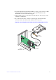
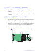
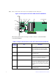
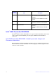
Note: Pin 1 on the headers and connectors is highlighted in red in this figure.
Figure 12. Card Layout for the Intel
®
RAID Controller RS3MC044
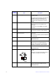
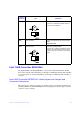
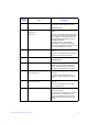
The following table describes the jumpers and the connectors on the Intel
®
RAID
Controller RS3MC044.
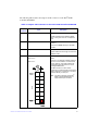
Table 6. Jumpers and Connectors on the Intel
®
RAID Controller RS3MC044
Jumper/
Connector
Type Description
J1A4 3-pin connector IPMI-style I
2
C connector for Ports 4 to 7.
Supports SCSI Enclosure Services (SES)
over I
2
C through an internal I
2
C backplane
cable.
J1A5 2-pin connector Default Serial boot ROM (SBR) header.
Reserved for use.
J1A6 2-pin connector Global drive fault LED header.
Connects to an LED that indicates activity on
the drives connected to the controller.
J1A7 2-pin connector Cache write pending header.
Connector for an LED mounted on the system
enclosure. The LED indicates that the data in
the cache has yet to be written to the storage
devices.
J1A8 5-pin connector CPLD header.
Reserved for use.
3_02173-00
J1A11
J1B2
J2B4
J6B1
J1A6
J1A8
J1B1
J1A7
J1A5
J1A12
J1A4 J1A9
J2A1
J1A10
J4A1
J2L1 (Rear Side)