
Hardware User Guide


29 12Gb/s Intel® RAID Controllers User Guide
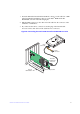
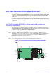
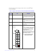
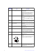
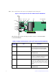
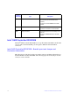
J2B4 Standard edge card connector The interface between the RAID controller and
the host system.
Along with the PCIe interface, this connector
provides power to the board and an I
2
C
interface connected to the I
2
C bus for the
Intelligent Platform Management Interface
(IPMI).
J3L1 20-pin connector Remote RAID Maintenance Free Backup
Units connector (on the backside of the
controller).
Connects the remote RMFBU to the RAID
controller.
J4B1 70-pin connector Flash Module DDR3 Interface.
Connects the controller to a flash module.
J5A1 Dual x4 SAS Port 0 through Port 7
internal connector
Two SFF-8643 mini-SAS HD-4i internal
connectors.
Connects the controller by cable to SAS drives
or SATA drives.
J5B1 2-pin connector Test header.
Reserved for use.
J6B1 3-pin header Premium Feature Key header.
Enables support for selected advanced
features, such as Recovery, CacheCade*,
FastPath, and SafeStore* disk encryption.
J6B2 2-pin connector Default Serial boot ROM (SBR) header.
Reserved for use.
J6B3 2-pin connector Global hard disk drive (HDD) activity LED
header.
Connects to an LED that indicates activity on
the drives connected to the controller.
J6B4 4-pin connector On-board Serial Universal Asynchronous
Receiver/Transmitter (UART) connector.
Reserved for use.
Jumper/
Connector
Type Description