
Hardware user guide


18 Intel® Integrated RAID Module RMS25KB0x0 and RMS25JB0x0 Hardware User’s Guide
Note: The RAID controller in this document doesn't ship with SAS/SATA cables. Users can
separately order the SAS/SATA cable accessory kit as
needed. Please see the Tested
Operating System List for available cable accessory kits at
http://www.intel.com/p/en_US/support/server/.
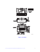
PCI Interface
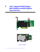
Intel
®
Integrated RAID Module RMS25KB080 and RMS25KB040 must be installed into
a standard x8 or larger PCI Express* slot that complies with the PCI Express
Specification, Revision 3.0. The controller is PCI Express* 1.0 and 2.0 compatible and is
backward-compatible with x8 or larger slots that are wired with x1, x2, and x4 PCI
Express* lanes.
Note: The modules will
support PCI Express* Revision 3.0 at post launch.
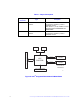
Host Board Interface
Intel
®
Integrated RAID Module RMS25JB080 and RMS25JB040 board interface with the
host system through one custom board-to-board interface that implements one x8 PCI
Express* lanes signaling as defined in the PCI Express Specification 3.0. These interfaces
also provide +3.3 V power to the board.
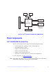
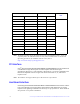
A12 GND 7 GND Port 2
A13 RX2+ 6 TX+
A14 RX2- 5 TX-
B12 GND 4 GND
B13 TX2+ 2 RX+
B14 TX2- 3 RX-
B15 GND 1 GND
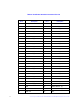
A15 GND 7 GND Port 3
A16 RX3+ 6 TX+
A17 RX3- 5 TX-
A18 GND 4 GND
B16 TX3+ 2 RX+
B17 TX3- 3 RX-
B18 GND 1 GND
Controller Connector Pin-out Backplane Connector Pin-out
Po
rt
SFF-8087 Pin # Pin Definition Pin # Pin Definition