
Hardware user guide

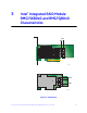


16 Intel® Integrated RAID Module RMS25KB0x0 and RMS25JB0x0 Hardware User’s Guide
Flash ROM
An 16-MB CFI-compliant flash ROM is used to accommodate RAID firmware and RAID
BIOS Console 2 OpROM.
Boot Strap ROM (SEEPROM)
The serial bootstrap ROM is used to configure the LSI* LSISAS2308 Processor Chip
before the server board configures the PCI Express* registers. The bootstrap ROM sets
the Phase Lock Loop (PLL) dividers, bootstrap configuration, and so on.
NVSRAM
A 32-KB NVSRAM is used to store disk and drive setup information.
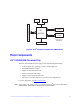
Diagnostic Components
LED Placement and Function
The Intel
®
Integrated RAID Module RMS25KB080, RMS25KB040, RMS25JB080 and
RMS25JB040 contain the following LEDs:
• One surface-mounted heartbeat LED (Green Color) to indicate SAS2208 activity.
• Another two surface-mounted system error LEDs (Amber Color) to indicate a
board error.
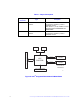
SAS/SATA Connectors
The Intel
®
Integrated RAID Module RMS25KB080 and RMS25JB080 provide two
internal SFF8087 SAS/SATA signal connectors. The Intel
®
Integrated RAID Module
RMS25KB080 and RMS25JB080 provide one internal SFF8087 SAS/SATA signal
connector. Each SFF8087 connector provides support for four SAS/SATA ports. The
sideband signals are configured to adhere to the SFF-8485 Specifications for SGPIO
support.
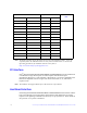
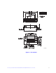
Figure 10. Internal SFF8087 SAS/SATA signal connectors
Internal connector