
Hardware User's Guide


32 Intel® Integrated RAID Module RMS25PB0x0 and RMS25CB0x0 Hardware User’s Guide
Electrical Characteristics
All power is supplied to the adapter via the PCI Express 3.3V and 12V rail. Necessary
Voltages are provided by onboard switching regulator circuitry operating off of 12V and
3.3V rails.
The following states determine the typical current consumption of the board:
• State 1. During BBU fast charge
• State 2. During initialization of all RAID 5 logical drives simultaneously
• State 3. While sitting idle at the DOS prompt.
— Supply voltage = 12V +/- 8% (from PCI edge connector only)
— Supply voltage = 3.3V +/- 9% (from PCI edge connector only)
— Actual power consumption.
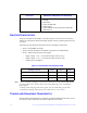
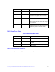
Table 10. Actual Power Consumption Table
Note: +12V is used in the charging circuitry for the battery pack on the optional BBU Remote
card. If the BBU remote card is cable connected the following power consumption
figures apply:
1. During trickle charging of the battery pack: N/A (no trickle charge for Li-ION
2. During fast charging of the battery pack: 250mA rise in +12V current
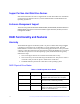
Thermal and Atmospheric Characteristics
The maximum board temperature is limited by the LSI SAS2208 ROC Processor since it
uses the most power and will be the hottest component on the board.
Error Checking and Indication • Parity generation and checking, automatic consistency
checking
• Patrol reads
• Activity and fault LEDs
• Multiple retries
• Logs in NVRAM, event log, CIM, Smart, Intel
®
RAID
Web Console 2
Specification
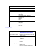
Intel
®
Integrated RAID Module RMS25PB080,
RMS25PB040, RMS25CB080 and RMS25CB040
PCI Edge connector State1 State 2 State 3
3.3V supply 0.96A 0.86A 0.92A
+12V supply 0.81A 0.55A 0.56A
3.3V AUX. supply (BBU Applications only) 0.38A 0.2A 0.02A