
Datasheet


Mobile Intel
®
Celeron
®
Processor (0.13 µ)
Micro-FCBGA and Micro-FCPGA Packages Datasheet
298517-006 Datasheet 97
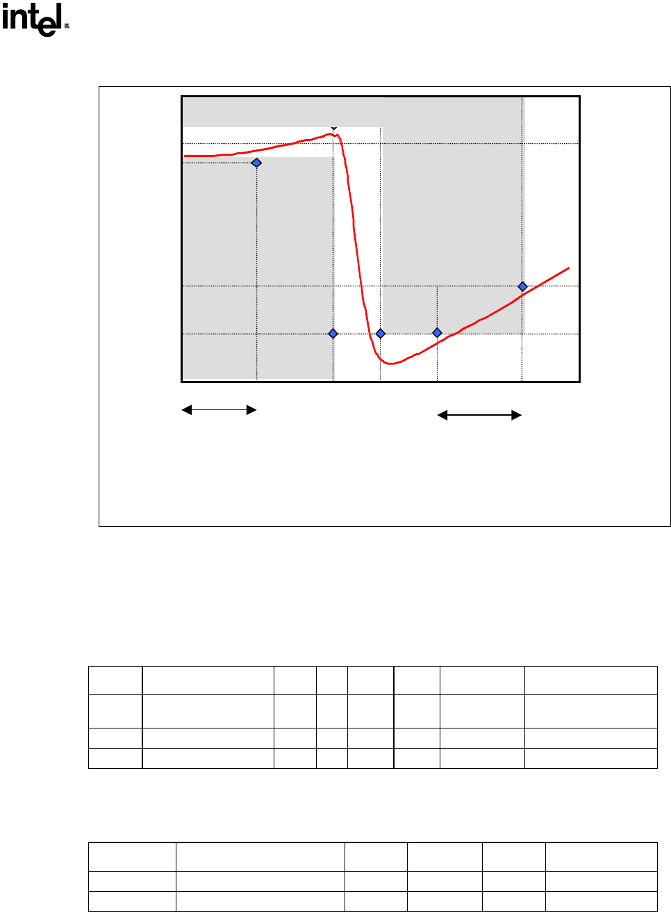
Figure 32. PLL Filter Specifications
0 dB
-28 dB
-34 dB
0.2 dB
Forbidden
zone
x dB
Forbidden
zone
1 MHz 66 MHz fcore fpeak1 HzDC
Passband
High Frequency
Band
x = 20.log[(Vcct-60 mV)/ Vcct]
NOTES:
Diagram is not to scale
No specification for frequencies beyond fcore.
Fpeak, if existent, should be less than 0.05 MHz.
A3. Recommendation for Mobile Systems
The following LC components are recommended. The tables will be updated as other suitable
components and specifications are identified.
Table 56. PLL Filter Inductor Recommendations
Inductor Part Number Value Tol SRF Rated I DCR Min Damping R Needed
L1 TDK MLF2012A4R7KT
4.7
µH
10% 35 MHz 30 mA
0.56
Ω (1Ω
max)
0
Ω
L2 Murata LQG21N4R7K10
4.7
µH
10% 47 MHz 30 mA
0.7 Ω (+/-50%) 0 Ω
L3 Murata LQG21C4R7N00
4.7
µH
30% 35 MHz 30 mA
0.3 Ω max 0.2 Ω (assumed)
NOTE: Minimum damping resistance is calculated from 0.35 Ω – DCR
min
. From vendor provided data, L1 and L2
DCR
min
is 0.4Ω and 0.5Ω respectively, qualifying them for zero required trace resistance. DCR
min
for L3 is
not known and is assumed to be 0.15
Ω. Products with equivalent specifications may also be used.
Table 57. PLL Filter Capacitor Recommendations
Capacitor Part Number Value Tolerance ESL ESR
C1 Kemet T495D336M016AS
33
µF
20% 2.5 nH
0.225 Ω
C2 AVX TPSD336M020S0200
33
µF
20% unknown
0.2 Ω