
Datasheet


Mobile Intel
®
Celeron
®
Processor (0.13 µ) in
Micro-FCBGA and Micro-FCPGA Packages Datasheet
40 Datasheet 298517-006
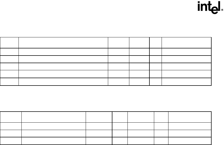
Table 22. AGTL Signal Group DC Specifications
Symbol Parameter Min Max Unit Notes
V
IL
Input Low Voltage -0.15 V
REF
-0.2 V
V
IH
Input High Voltage V
REF
+0.2 V
CCT
V See V
CCT,max
in Table 11
V
OH
Output High Voltage — — V See V
CCT,max
in Table 11
R
ON
Output Low Drive Strength 16.67
Ω
Note 2
I
L
Leakage Current for Inputs, Outputs and I/Os 100
µA
Note 1
NOTES:
1. Specification applies to leakage high only, for pins with on die R
TT
, (0 < V
IN/OUT
≤ V
CCT
).
2. Refer to IBIS models for I/V characteristics.
Table 23. AGTL Bus DC Specifications
Symbol Parameter Min Typ Max Unit Notes
V
CCT
Bus Termination Voltage 1.25 V Note 1
V
REF
Input Reference Voltage
2
/
3
V
CCT
– 2%
2
/
3
V
CCT
2
/
3
V
CCT
+ 2% V ±2%, Note 2
R
TT
Bus Termination Strength 50 56 65
Ω
On-die R
TT
, Note 3
NOTES:
1. Please refer to Table 11 for minimum and maximum values.
2. V
REF
should be created from V
CCT
by a voltage divider.
3. The RESET# signal does not have an on-die R
TT
. It requires an off-die 56.2 Ω ±1% terminating resistor
connected to V
CCT
.