
User Manual

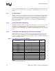
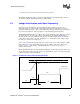
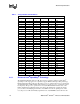
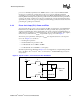
Table Of Contents
- Legal - Information in this document is provided solely to enable use of Intel products. Intel assumes no liability whatsoever, including infringement of any patent or copyright, for sale and use of Intel products except as provided in Intel'...
- Legal - Actual system-level properties, such as skin temperature, are a function of various factors, including component placement, component power characteristics, system power and thermal management techniques, software application usage an...
- Legal - Information in this document is provided in connection with Intel products. No license, express or implied, by estoppel or otherwise, to any intellectual property rights is granted by this document. Except as provided in Intel’s Terms...
- Legal - Intel may make changes to specifications and product descriptions at any time, without notice.
- Legal - Designers must not rely on the absence or characteristics of any features or instructions marked “reserved” or “undefined.” Intel reserves these for future definition and shall have no responsibility whatsoever for conflicts or incomp...
- Legal - The Mobile Intel Pentium 4 Processor-M may contain design defects or errors known as errata which may cause the product to deviate from published specifications. Current characterized errata are available on request.
- Legal - Contact your local Intel sales office or your distributor to obtain the latest specifications and before placing your product order.
- Legal - Copies of documents which have an ordering number and are referenced in this document, or other Intel literature, may be obtained by calling 1-800-548-4725 or by visiting Intel’s Website at http://www.intel.com
- Legal - Copyright © Intel Corporation 2000-2003.
- Legal - Intel, Pentium, Intel NetBurst, and SpeedStep are registered trademarks or trademarks of Intel Corporation and its subsidiaries in the United States and other countries.
- Legal - * Other brands and names are the property of their respective owners.
- 02_TOCHead - Contents
- 01_LevelTOC - 1. Introduction 9
- 01_LevelTOC - 2. Electrical Specifications 13
- 01_LevelTOC - 3. System Bus Signal Quality Specifications 51
- 01_LevelTOC - 4. Package Mechanical Specifications 61
- 01_LevelTOC - 5. Pin Listing and Signal Definitions 67
- 01_LevelTOC - 6. Thermal Specifications and Design Considerations 89
- 01_LevelTOC - 7. Configuration and Low Power Features 93
- 01_LevelTOC - 8. Debug Tools Specifications 97
- 01_LevelTOC -
- 03_TOCHead - Figures
- 03_TOCHead - Tables
- 03_TOCHead - Revision History
- Title - Mobile Intel‚ Pentium‚ 4 Processor-M
- 01_Level - 1. Introduction
- 01_Level - 2. Electrical Specifications
- 02_Level - 2.1 System Bus and GTLREF
- 02_Level - 2.2 Power and Ground Pins
- 02_Level - 2.3 Decoupling Guidelines
- 02_Level - 2.4 Voltage Identification and Power Sequencing
- 05_Figure - Figure 1. VCCVID Pin Voltage and Current Requirements
- 06_Table - Table 3. Voltage Identification Definition
- 03_Level - 2.4.1 Enhanced Intel® SpeedStep® Technology
- 03_Level - 2.4.2 Phase Lock Loop (PLL) Power and Filter
- 03_Level - 2.4.3 Catastrophic Thermal Protection
- 02_Level - 2.5 Signal Terminations, Unused Pins and TESTHI[10:0]
- 02_Level - 2.6 System Bus Signal Groups
- 06_Table - Table 4. System Bus Pin Groups
- TableNotes - NOTES:
- TableStep1 - 1. Refer to Section 5.2 for signal descriptions.
- TableStepn - 2. These AGTL+ signals do not have on-die termination. Refer to Section 2.5 for termination requirements.
- TableStepn - 3. In processor systems where there is no debug port implemented on the system board, these signals are used to support a debug port interposer. In systems with the debug port implemented on the system board, these signals are no connects.
- TableStepn - 4. These signal groups are not terminated by the processor. Signals not driven by the ICH3-M component must be terminated on the system board. Refer to Section 2.5 and the Mobile Intel‚ Pentium‚ 4 Processor-M and Intel‚ 845MP/845...
- TableStepn - 5. The value of these pins during the active-to-inactive edge of RESET# defines the processor configuration options. See Section 7.1 for details.
- 06_Table - Table 4. System Bus Pin Groups
- 02_Level - 2.7 Asynchronous GTL+ Signals
- 02_Level - 2.8 Test Access Port (TAP) Connection
- 02_Level - 2.9 System Bus Frequency Select Signals (BSEL[1:0])
- 02_Level - 2.10 Maximum Ratings
- 02_Level - 2.11 Processor DC Specifications
- 06_Table - Table 7. Voltage and Current Specifications
- TableNotes - NOTES:
- TableStep1 - 1. Unless otherwise noted, all specifications in this table are based on latest post-silicon measurements available at the time of publication.
- TableStepn - 2. These voltages are targets only. A variable voltage source should exist on systems in the event that a different voltage is required. See Section 2.4 and Table 3 for more information. The VID bits will set the typical VCC with...
- TableStepn - 3. The voltage specification requirements are measured at the system board socket ball with a 100 MHz bandwidth oscilloscope, 1.5 pF maximum probe capacitance, and 1 MW minimum impedance. The maximum length of ground wire on the ...
- TableStepn - 4. Refer to Table 8 to Table 11 and Figure 4 to Figure 6 for the minimum, typical, and maximum VCC (measured at the system board socket ball) allowed for a given current. The processor should not be subjected to any VCC and ICC c...
- TableStepn - 5. VCC_MIN is defined at ICC_MAX.
- TableStepn - 6. The current specified is also for AutoHALT State.
- TableStepn - 7. Typical VCC indicates the VID encoded voltage. Voltage supplied must conform to the load line specification shown in Table 8 to Table 11.
- TableStepn - 8. The maximum instantaneous current the processor will draw while the thermal control circuit is active as indicated by the assertion of PROCHOT# is the same as the maximum ICC for the processor.
- TableStepn - 9. Maximum specifications for ICC Core, ICC Stop-Grant, ICC Sleep, and ICC Deep Sleep are specified at VCC Static Max. derived from the tolerances in Table 8 through Table 11, TJ Max., and under maximum signal loading conditions.
- TableStepn - 10. The specification is defined per PLL pin.
- TableStepn - 11. The voltage response to a processor current load step (transient) must stay within the Transient Voltage Tolerance Window. The voltage surge or droop response measured in this window is typically on the order of several hundr...
- TableStepn - 12. This specification applies to both static and transient components. The rising edge of VCCVID must be monotonic from 0 to 1.1 V. See Figure 1 for current requirements. In this case, monotonic is defined as continuously increa...
- 06_Table - Table 8. IMVP-III Voltage Regulator Tolerances for VID = 1.30 V Operating Mode (Maximum Performance Mode)
- 05_Figure - Figure 4. Illustration of VCC Static and Transient Tolerances (VID = 1.30 V)
- 06_Table - Table 9. IMVP-III Voltage Regulator Tolerances for VID = 1.20 V Operating Mode (Battery Optimized Mode)
- 05_Figure - Figure 5. Illustration of VCC Static and Transient Tolerances (VID = 1.20 V)
- 06_Table - Table 10. IMVP-III Deep Sleep State Voltage Regulator Tolerances for Maximum Performance Mode (VID = 1.30 V, VID Offset = 4.62%)
- 06_Table - Table 11. IMVP-III Deep Sleep State Voltage Regulator Tolerances for Battery Optimized Mode (VID = 1.20 V, VID Offset = 4.62%)
- 05_Figure - Figure 6. Illustration of Deep Sleep VCC Static and Transient Tolerances (VID Setting = 1.30 V)
- 06_Table - Table 12. System Bus Differential BCLK Specifications
- TableNotes - NOTES:
- TableStep1 - 1. Unless otherwise noted, all specifications in this table apply to all processor frequencies.
- TableStepn - 2. Crossing voltage is defined as the instantaneous voltage value when the rising edge of BCLK0 equals the falling edge of BCLK1.
- TableStepn - 3. VHavg is the statistical average of the VH measured by the oscilloscope .
- TableStepn - 4. Overshoot is defined as the absolute value of the maximum voltage.
- TableStepn - 5. Undershoot is defined as the absolute value of the minimum voltage.
- TableStepn - 6. Ringback Margin is defined as the absolute voltage difference between the maximum Rising Edge Ringback and the maximum Falling Edge Ringback.
- TableStepn - 7. Threshold Region is defined as a region entered around the crossing point voltage in which the differential receiver switches. It includes input threshold hysteresis.
- TableStepn - 8. The crossing point must meet the absolute and relative crossing point specifications simultaneously.
- TableStepn - 9. VHavg can be measured directly using "Vtop" on Agilent* scopes and "High" on Tektronix* scopes.
- TableStepn - 10. DVCROSS is defined as the total variation of all crossing voltages as defined in note 2.
- 06_Table - Table 13. AGTL+ Signal Group DC Specifications
- TableNotes - NOTES:
- TableStep1 - 1. Unless otherwise noted, all specifications in this table apply to all processor frequencies.
- TableStepn - 2. VIL is defined as the maximum voltage level at a receiving agent that will be interpreted as a logical low value.
- TableStepn - 3. VIH is defined as the minimum voltage level at a receiving agent that will be interpreted as a logical high value.
- TableStepn - 4. VIH and VOH may experience excursions above VCC. However, input signal drivers must comply with the signal quality specifications in Section 3.
- TableStepn - 5. Refer to processor I/O Buffer Models for I/V characteristics.
- TableStepn - 6. The VCC referred to in these specifications is the instantaneous VCC.
- TableStepn - 7. Vol max of 0.450 Volts is guaranteed when driving into a test load of 50 W as indicated in Figure 8.
- TableStepn - 8. Leakage to VSS with pin held at VCC.
- TableStepn - 9. Leakage to VCC with pin held at 300 mV.
- 06_Table - Table 14. Asynchronous GTL+ Signal Group DC Specifications
- TableNotes - NOTES:
- TableStep1 - 1. Unless otherwise noted, all specifications in this table apply to all processor frequencies.
- TableStepn - 2. All outputs are open-drain.
- TableStepn - 3. VIH and VOH may experience excursions above VCC. However, input signal drivers must comply with the signal quality specifications in Section 3.
- TableStepn - 4. The VCC referred to in these specifications refers to instantaneous VCC.
- TableStepn - 5. This specification applies to the asynchronous GTL+ signal group.
- TableStepn - 6. The maximum output current is based on maximum current handling capability of the buffer and is not specified into the test load shown in Figure 8.
- TableStepn - 7. Refer to the processor I/O Buffer Models for I/V characteristics.
- TableStepn - 8. Vol max of 0.270 Volts is guaranteed when driving into a test load of 50 W as indicated in Figure 8 for the Asynchronous GTL+ signals.
- TableStepn - 9. Leakage to VSS with pin held at VCC.
- TableStepn - 10. Leakage to VCC with pin held at 300 mV.
- 06_Table - Table 15. PWRGOOD and TAP Signal Group DC Specifications
- TableNotes - NOTES:
- TableStep1 - 1. Unless otherwise noted, all specifications in this table apply to all processor frequencies.
- TableStepn - 2. All outputs are open-drain.
- TableStepn - 3. TAP signal group must comply with the signal quality specifications in Section 3.
- TableStepn - 4. Refer to I/O Buffer Models for I/V characteristics.
- TableStepn - 5. The VCC referred to in these specifications refers to instantaneous VCC.
- TableStepn - 6. The maximum output current is based on maximum current handling capability of the buffer and is not specified into the test load shown if Figure 8.
- TableStepn - 7. Vol max of 0.320 Volts is guaranteed when driving into a test load of 50 Ohms as indicated in Figure 8 for the TAP Signals.
- TableStepn - 8. VHYS represents the amount of hysteresis, nominally centered about 1/2 Vcc for all TAP inputs.
- TableStepn - 9. Leakage to VSS with pin held at VCC.
- TableStepn - 10. Leakage to VCC with pin held at 300 mV.
- 06_Table - Table 16. ITPCLKOUT[1:0] DC Specifications
- 05_Figure - Figure 7. ITPCLKOUT[1:0] Output Buffer Diagram
- 06_Table - Table 17. BSEL [1:0] and VID[4:0] DC Specifications
- 06_Table - Table 7. Voltage and Current Specifications
- 02_Level - 2.12 AGTL+ System Bus Specifications
- 06_Table - Table 18. AGTL+ Bus Voltage Definitions
- TableNotes - NOTES:
- TableStep1 - 1. Unless otherwise noted, all specifications in this table apply to all processor frequencies.
- TableStep1 - 2. The tolerances for this specification have been stated generically to enable the system designer to calculate the minimum and maximum values across the range of VCC.
- TableStep1 - 3. GTLREF should be generated from VCC by a voltage divider of 1% tolerance resistors or 1% tolerance matched resistors. Refer to the Mobile Intel‚ Pentium‚ 4 Processor-M and Intel‚ 845MP/845MZ Chipset Platform Design Guide for i...
- TableStep1 - 4. RTT is the on-die termination resistance measured at VOL of the AGTL+ output driver. Refer to processor I/O buffer models for I/V characteristics.
- TableStep1 - 5. COMP resistance must be provided on the system board with 1% tolerance resistors. See the Mobile Intel‚ Pentium‚ 4 Processor-M and Intel‚ 845MP/845MZ Chipset Platform Design Guide for implementation details.
- TableStep1 - 6. The VCC referred to in these specifications is the instantaneous VCC.
- 06_Table - Table 18. AGTL+ Bus Voltage Definitions
- 02_Level - 2.13 System Bus AC Specifications
- 06_Table - Table 19. System Bus Differential Clock Specifications
- TableNotes - NOTES:
- TableStep1 - 1. Unless otherwise noted, all specifications in this table apply to all processor frequencies.
- TableStep1 - 2. The period specified here is the average period. A given period may vary from this specification as governed by the period stability specification (T2).
- TableStep1 - 3. In this context, period stability is defined as the worst case timing difference between successive crossover voltages. In other words, the largest absolute difference between adjacent clock periods must be less than the period stability.
- TableStep1 - 4. Slew rate is measured between the 35% and 65% points of the clock swing (VL to VH).
- 06_Table - Table 20. System Bus Common Clock AC Specifications
- TableNotes - NOTES:
- TableStep1 - 1. Unless otherwise noted, all specifications in this table apply to all processor frequencies.
- TableStep1 - 2. Not 100% tested. Specified by design characterization.
- TableStep1 - 3. All common clock AC timings for AGTL+ signals are referenced to the Crossing Voltage (VCROSS) of the BCLK[1:0] at rising edge of BCLK0. All common clock AGTL+ signal timings are referenced at GTLREF at the processor core.
- TableStep1 - 4. Valid delay timings for these signals are specified into the test circuit described in Figure 8 and with GTLREF at 2/3 VCC ± 2%.
- TableStep1 - 5. Specification is for a minimum swing defined between AGTL+ VIL_MAX to VIH_MIN. This assumes an edge rate of 0.4 V/ns to 4.0 V/ns.
- TableStep1 - 6. RESET# can be asserted asynchronously, but must be deasserted synchronously.
- TableStep1 - 7. This should be measured after VCC and BCLK[1:0] become stable.
- TableStep1 - 8. Maximum specification applies only while PWRGOOD is asserted.
- 06_Table - Table 21. System Bus Source Synch AC Specifications AGTL+ Signal Group
- TableNotes - NOTES:
- TableStep1 - 1. Unless otherwise noted, all specifications in this table apply to all processor frequencies and cache sizes.
- TableStepn - 2. Not 100% tested. Specified by design characterization.
- TableStepn - 3. All source synchronous AC timings are referenced to their associated strobe at GTLREF. Source synchronous data signals are referenced to the falling edge of their associated data strobe. Source synchronous address signals are ...
- TableStepn - 4. Unless otherwise noted these specifications apply to both data and address timings.
- TableStepn - 5. Valid delay timings for these signals are specified into the test circuit described in Figure 8 and with GTLREF at 2/3 VCC ± 2%.
- TableStepn - 6. Specification is for a minimum swing defined between AGTL+ VIL_MAX to VIH_MIN. This assumes an edge rate of 0.3 V/ns to 4.0V /ns.
- TableStepn - 7. All source synchronous signals must meet the specified setup time to BCLK as well as the setup time to each respective strobe.
- TableStepn - 8. This specification represents the minimum time the data or address will be valid before its strobe. Refer to the Mobile Intel‚ Pentium‚ 4 Processor-M and Intel‚ 845MP/845MZ Chipset Platform Design Guide for more information on...
- TableStepn - 9. This specification represents the minimum time the data or address will be valid after its strobe. Refer to the Mobile Intel‚ Pentium‚ 4 Processor-M and Intel‚ 845MP/845MZ Chipset Platform Design Guide for more information on ...
- TableStepn - 10. The rising edge of ADSTB# must come approximately 1/2 BCLK period (5 ns) after the falling edge of ADSTB#.
- TableStepn - 11. For this timing parameter, n = 1, 2, and 3 for the second, third, and last data strobes respectively.
- TableStepn - 12. The second data strobe (falling edge of DSTBn#) must come approximately 1/4 BCLK period (2.5 ns) after the first falling edge of DSTBp#. The third data strobe (falling edge of DSTBp#) must come approximately 2/4 BCLK period (...
- TableStepn - 13. This specification applies only to DSTBN[3:0]# and is measured to the second falling edge of the strobe.
- 06_Table - Table 22. Miscellaneous Signals AC Specifications
- TableNotes - NOTES:
- TableStep1 - 1. Unless otherwise noted, all specifications in this table apply to all processor frequencies.
- TableStepn - 2. All AC timings for the Asynch GTL+ signals are referenced to the BCLK0 rising edge at Crossing Voltage. All Asynch GTL+ signal timings are referenced at GTLREF. PWRGOOD is referenced to the BCLK0 rising edge at 0.5*VCC
- TableStepn - 3. These signals may be driven asynchronously.
- TableStepn - 4. Refer to the PWRGOOD definition for more details regarding the behavior of this signal.
- TableStepn - 5. Length of assertion for PROCHOT# does not equal internal clock modulation time. Time is allocated after the assertion and before the deassertion of PROCHOT# for the processor to complete current instruction execution. This spe...
- TableStepn - 6. See Section 7.2 for additional timing requirements for entering and leaving the low power states.
- 06_Table - Table 23. System Bus AC Specifications (Reset Conditions)
- 06_Table - Table 24. TAP Signals AC Specifications
- TableNotes - NOTES:
- TableStep1 - 1. Unless otherwise noted, all specifications in this table apply to all processor frequencies.
- TableStepn - 2. Not 100% tested. Specified by design characterization.
- TableStepn - 3. All AC timings for the TAP signals are referenced to the TCK signal at 0.5*VCC at the processor pins. All TAP signal timings (TMS, TDI, etc) are referenced at 0.5*VCC at the processor pins.
- TableStepn - 4. Rise and fall times are measured from the 20% to 80% points of the signal swing.
- TableStepn - 5. Referenced to the rising edge of TCK.
- TableStepn - 6. Referenced to the falling edge of TCK.
- TableStepn - 7. Specifications for a minimum swing defined between TAP VT- to VT+. This assumes a minimum edge rate of 0.5 V/ns
- TableStepn - 8. TRST# must be held asserted for 2 TCK periods to be guaranteed that it is recognized by the processor.
- TableStepn - 9. It is recommended that TMS be asserted while TRST# is being deasserted.
- 06_Table - Table 25. ITPCLKOUT[1:0] AC Specifications
- 06_Table - Table 26. Stop Grant/Sleep/Deep Sleep/Enhanced Intel SpeedStep Technology AC Specifications
- 06_Table - Table 19. System Bus Differential Clock Specifications
- 02_Level - 2.14 Processor AC Timing Waveforms
- TableNotes - NOTES:
- TableStep1 - 1. All common clock AC timings for AGTL+ signals are referenced to the Crossing Voltage (VCROSS) of the BCLK[1:0] at rising edge of BCLK0. All common clock AGTL+ signal timings are referenced at GTLREF at the processor core.
- TableStep1 - 2. All source synchronous AC timings for AGTL+ signals are referenced to their associated strobe (address or data) at GTLREF. Source synchronous data signals are referenced to the falling edge of their associated data strobe. Sou...
- TableStep1 - 3. All AC timings for AGTL+ strobe signals are referenced to BCLK[1:0] at VCROSS. All AGTL+ strobe signal timings are referenced at GTLREF at the processor core silicon.
- TableStep1 - 4. All AC timings for the TAP signals are referenced to the TCK signal at 0.5*VCC at the processor pins. All TAP signal timings (TMS, TDI, etc.) are referenced at 0.5*VCC at the processor pins.
- 05_Figure - Figure 8. AC Test Circuit
- 05_Figure - Figure 9. TCK Clock Waveform
- 05_Figure - Figure 10. Differential Clock Waveform
- 05_Figure - Figure 11. Differential Clock Crosspoint Specification
- 05_Figure - Figure 12. System Bus Common Clock Valid Delay Timings
- 05_Figure - Figure 13. System Bus Reset and Configuration Timings
- 05_Figure - Figure 14. Source Synchronous 2X (Address) Timings
- 05_Figure - Figure 15. Source Synchronous 4X Timings
- 05_Figure - Figure 16. Power Up Sequence
- 05_Figure - Figure 17. Power Down Sequence
- 05_Figure - Figure 18. Test Reset Timings
- 05_Figure - Figure 19. THERMTRIP# to Vcc Timing
- 05_Figure - Figure 20. FERR#/PBE# Valid Delay Timing
- 05_Figure - Figure 21. TAP Valid Delay Timing
- 05_Figure - Figure 22. ITPCLKOUT Valid Delay Timing
- 05_Figure - Figure 23. Stop Grant/Sleep/Deep Sleep Timing
- 05_Figure - Figure 24. Enhanced Intel SpeedStep Technology/Deep Sleep Timing
- 01_Level - 3. System Bus Signal Quality Specifications
- 02_Level - 3.1 System Bus Clock (BCLK) Signal Quality Specifications and Measurement Guidelines
- 06_Table - Table 27. BCLK Signal Quality Specifications
- TableNotes - NOTES:
- TableStep1 - 1. Unless otherwise noted, all specifications in this table apply to all Mobile Intel Pentium 4 Processor-M frequencies.
- TableStep1 - 2. The rising and falling edge ringback voltage specified is the minimum (rising) or maximum (falling) absolute voltage the BCLK signal can dip back to after passing the VIH (rising) or VIL (falling) voltage limits. This specific...
- 05_Figure - Figure 25. BCLK Signal Integrity Waveform
- 06_Table - Table 27. BCLK Signal Quality Specifications
- 02_Level - 3.2 System Bus Signal Quality Specifications and Measurement Guidelines
- 06_Table - Table 28. Ringback Specifications for AGTL+ and Asynchronous GTL+ Signal Groups
- TableNotes - NOTES:
- TableStep1 - 1. All signal integrity specifications are measured at the processor silicon (pads).
- TableStep1 - 2. Unless otherwise noted, all specifications in this table apply to all Mobile Intel Pentium 4 Processor-M frequencies.
- TableStep1 - 3. Specifications are for the edge rate of 0.3 - 4.0 V/ns.
- TableStep1 - 4. All values specified by design characterization.
- TableStep1 - 5. Please see Section 3.3 for maximum allowable overshoot.
- TableStep1 - 6. Ringback between GTLREF + 10% and GTLREF - 10% is not supported.
- TableStep1 - 7. Intel recommends simulations not exceed a ringback value of GTLREF +/- 200 mV to allow margin for other sources of system noise.
- 06_Table - Table 29. Ringback Specifications for PWRGOOD Input and TAP Signal Groups
- TableNotes - NOTES:
- TableStep1 - 1. All signal integrity specifications are measured at the processor silicon.
- TableStepn - 2. Unless otherwise noted, all specifications in this table apply to all Mobile Intel Pentium 4 Processor-M frequencies.
- TableStepn - 3. Please see Section 3.3 for maximum allowable overshoot.
- TableStepn - 4. Please see Section 2.11 for the DC specifications.
- 05_Figure - Figure 26. Low-to-High System Bus Receiver Ringback Tolerance
- 05_Figure - Figure 27. High-to-Low System Bus Receiver Ringback Tolerance
- 05_Figure - Figure 28. Low-to-High System Bus Receiver Ringback Tolerance for PWRGOOD and TAP Buffers
- 05_Figure - Figure 29. High-to-Low System Bus Receiver Ringback Tolerance for PWRGOOD and TAP Buffers
- 06_Table - Table 28. Ringback Specifications for AGTL+ and Asynchronous GTL+ Signal Groups
- 02_Level - 3.3 System Bus Signal Quality Specifications and Measurement Guidelines
- 03_Level - 3.3.1 Overshoot/Undershoot Guidelines
- 03_Level - 3.3.2 Overshoot/Undershoot Magnitude
- 03_Level - 3.3.3 Overshoot/Undershoot Pulse Duration
- 03_Level - 3.3.4 Activity Factor
- 03_Level - 3.3.5 Reading Overshoot/Undershoot Specification Tables
- Step1 - 1. Determine the signal group a particular signal falls into. If the signal is an AGTL+ signal operating in the common clock domain, use Table 32. For AGTL+ signals operating in the 2x source synchronous domain, use Table 31. For AGTL...
- Stepn - 2. Determine the magnitude of the overshoot (relative to VSS).
- Stepn - 3. Determine the activity factor (how often does this overshoot occur?)
- Stepn - 4. Next, from the appropriate specification table, determine the maximum pulse duration (in nanoseconds) allowed.
- Stepn - 5. Compare the specified maximum pulse duration to the signal being measured. If the pulse duration measured is less than the pulse duration shown in the table, then the signal meets the specifications.
- 03_Level - 3.3.6 Conformance Determination to Overshoot/Undershoot Specifications
- Step1 - 1. Ensure no signal ever exceeds VCC or -0.25 V OR
- Stepn - 2. If only one overshoot/undershoot event magnitude occurs, ensure it meets the over/undershoot specifications in the following tables OR
- Stepn - 3. If multiple overshoots and/or multiple undershoots occur, measure the worst case pulse duration for each magnitude and compare the results against the AF = 1 specifications. If all of these worst case overshoot or undershoot events...
- TableNotes - NOTES:
- TableStep1 - 1. Absolute Maximum Overshoot magnitude of 1.70 V must never be exceeded.
- TableStepn - 2. Absolute Maximum Overshoot is measured relative to VSS, Pulse Duration of overshoot is measured relative to VCC.
- TableStepn - 3. Absolute Maximum Undershoot and Pulse Duration of undershoot is measured relative to VSS.
- TableStepn - 4. Ringback below VCC can not be subtracted from overshoots/undershoots.
- TableStepn - 5. Lesser undershoot does not allocate longer or larger overshoot.
- TableStepn - 6. OEM's are strongly encouraged to follow Intel provided layout guidelines.
- TableStepn - 7. All values specified by design characterization.
- 06_Table - Table 30. Source Synchronous (400 MHz) AGTL+ Signal Group Overshoot/Undershoot Tolerance
- 06_Table - Table 31. Source Synchronous (200 MHz) AGTL+ Signal Group Overshoot/Undershoot Tolerance
- 06_Table - Table 32. Common Clock (100 MHz) AGTL+ Signal Group Overshoot/Undershoot Tolerance
- 06_Table - Table 33. Asynchronous GTL+, PWRGOOD Input, and TAP Signal Groups Overshoot/ Undershoot Tolerance
- 05_Figure - Figure 30. Maximum Acceptable Overshoot/Undershoot Waveform
- 02_Level - 3.1 System Bus Clock (BCLK) Signal Quality Specifications and Measurement Guidelines
- 01_Level - 4. Package Mechanical Specifications
- 05_Figure - Figure 31. Micro-FCPGA Package Top and Bottom Isometric Views
- 05_Figure - Figure 32. Micro-FCPGA Package Top and Side View
- 06_Table - Table 34. Micro-FCPGA Package Dimensions
- TableNotes - NOTES:
- TableStep1 - 1. All Dimensions are subject to change. Values shown are for reference only.
- TableStep1 - 2. Overall height with socket is based on design dimensions of the Micro-FCPGA package and socket with no thermal solution attached. Values were based on design specifications and tolerances. This dimension is subject to change b...
- 05_Figure - Figure 33. Micro-FCPGA Package - Bottom View
- 02_Level - 4.1 Processor Pin-Out
- 01_Level - 5. Pin Listing and Signal Definitions
- 01_Level - 6. Thermal Specifications and Design Considerations
- 06_Table - Table 38. Power Specifications for the Mobile Intel Pentium 4 Processor-M
- TableNotes - NOTES:
- TableStep1 - 1. TDP is defined as the worst case power dissipated by the processor while executing publicly available software under normal operating conditions at nominal voltages that meet the load line specifications. The TDP number shown ...
- TableStep1 - 2. Not 100% tested. These power specifications are determined by characterization of the processor currents at higher temperatures and extrapolating the values for the temperature indicated.
- TableStep1 - 3. The maximum junction temperature (TJ) is specified as the hottest location on the die. The thermal monitor’s automatic mode is used to indicate that the maximum TJ has been reached. Refer to Section 6.1.1 for TJ measurement gu...
- 02_Level - 6.1 Thermal Specifications
- 03_Level - 6.1.1 Thermal Diode
- Note - Note: The reading of the thermal sensor connected to the thermal diode does not reflect the temperature of the hottest location on the die (TJ). This is due to inaccuracies in the thermal diode, on-die temperature gradients between the...
- 06_Table - Table 39. Thermal Diode Interface
- 06_Table - Table 40. Thermal Diode Specifications
- TableNotes - NOTES:
- TableStep1 - 1. Intel does not support or recommend operation of the thermal diode under reverse bias.
- TableStepn - 2. Characterized at 100 C.
- TableStepn - 3. Not 100% tested. Specified by design characterization.
- TableStepn - 4. The ideality factor, n, represents the deviation from ideal diode behavior as exemplified by the diode equation: IFW=Is *(e(qVd/nkT) -1) Where IS = saturation current, q = electronic charge, VD = voltage across the diode, k = ...
- TableStepn - 5. The series resistance, RT, is provided to allow for a more accurate measurement of the diode junction temperature. RT as defined includes the pins of the processor but does not include any socket resistance or board trace resi...
- Note - Note: The reading of the thermal sensor connected to the thermal diode does not reflect the temperature of the hottest location on the die (TJ). This is due to inaccuracies in the thermal diode, on-die temperature gradients between the...
- 03_Level - 6.1.2 Thermal Monitor
- 03_Level - 6.1.1 Thermal Diode
- 06_Table - Table 38. Power Specifications for the Mobile Intel Pentium 4 Processor-M
- 01_Level - 7. Configuration and Low Power Features
- 01_Level - 8. Debug Tools Specifications
- 01_LevelTOC - 1. Introduction 9
- 01_LevelTOC - 2. Electrical Specifications 13
- 01_LevelTOC - 3. System Bus Signal Quality Specifications 51
- 01_LevelTOC - 4. Package Mechanical Specifications 61
- 01_LevelTOC - 5. Pin Listing and Signal Definitions 67
- 01_LevelTOC - 6. Thermal Specifications and Design Considerations 89
- 01_LevelTOC - 7. Configuration and Low Power Features 93
- 01_LevelTOC - 8. Debug Tools Specifications 97
Electrical Specifications
14 Mobile Intel
Pentium
4 Processor-M Datasheet
affect the long term reliability of the processor. For further information and design guidelines, refer
to the Mobile Intel
Pentium
4 Processor-M and Intel
845MP/845MZ Chipset Platform Design
Guide.
2.3.1 V
CC
Decoupling
Regulator solutions need to provide bulk capacitance with a low Effective Series Resistance (ESR)
and keep a low interconnect resistance from the regulator to the socket. Bulk decoupling for the
large current swings when the part is powering on, or entering/exiting low-power states, must be
provided by the voltage regulator solution. For more details on decoupling recommendations,
please refer to the Mobile Intel
Pentium
4 Processor-M and Intel
845MP/845MZ Chipset
Platform Design Guide.
2.3.2 System Bus AGTL+ Decoupling
The Mobile Intel Pentium 4 Processor-M integrates signal termination on the die and incorporates
high frequency decoupling capacitance on the processor package. Decoupling must also be
provided by the system motherboard for proper AGTL+ bus operation. For more information, refer
to the Mobile Intel
Pentium
4 Processor-M and Intel
845MP/845MZ Chipset Platform Design
Guide.
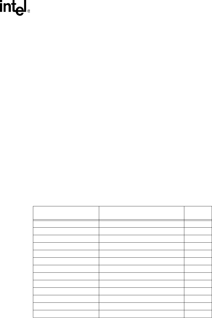
2.3.3 System Bus Clock (BCLK[1:0]) and Processor Clocking
BCLK[1:0] directly controls the system bus interface speed as well as the core frequency of the
processor. As in previous generation processors, the Mobile Intel Pentium 4 Processor-M core
frequency is a multiple of the BCLK[1:0] frequency. Refer to
Table 2 for the Mobile Intel Pentium
4 Processor-M supported ratios.
NOTES:
1. Ratio is used for debug purposes only.
Table 2. Core Frequency to System Bus Multipliers
Core Frequency
Multiplication of System Core Frequency
to System Bus Frequency
Notes
2
800 MHz 1/8 1
1.2 GHz 1/12
1.4 GHz 1/14
1.5 GHz 1/15
1.6 GHz 1/16
1.7 GHz 1/17
1.8 GHz 1/18
1.9 GHz 1/19
2.0 GHz 1/20
2.2 GHz 1/22
2.4 GHz 1/24
2.5 GHz 1/25
2.6 GHz 1/26