
Hardware User Guide


Intel® RAID SSD Cache Controller RCS25ZB040/RCS25ZB040LX User Guide 19
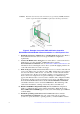
Life Status LED
The CR2 LED is mounted on the surface of the controller board. This LED is bicolor RED
or GREEN and it indicates the life status of the Nytro Flash modules. See Figure 8 for the
location of the CR2 LED.
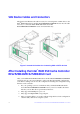
LEDs on the Backside of the board
CRB1 Orange LED = fault LED
CRB2 Blue LED = Status LED (whether off-loading or not)
CRB3 Green LED = power
Connectors
This section describes the connectors and headers on the Intel
®
RAID SSD Cache
Controller RCS25ZB040/RCS25ZB040LX card.
RAID Cache Protection Module Connector (J3)
J3 is for the connection for the RAID Cache Protection module. The module comes in the
optional RAID Maintenance Free Backup Unit 3. The kit comes complete including a
mounting bracket. The purpose of the RAID Cache Protection module is to protect
DRAM content on power failure.
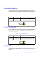
UART Connector (J5)
The UART connector debug port requires a special cable and Intel
®
support to gather
detailed Input/Output Controller (IOC) status.
Table 5. Intel
®
RAID SSD Cache Controller RCS25ZB040/RCS25ZB040LX
Card UART Pinout
Pin # Function
1 UART0_TX
2 Ground
3 UART0_RX
4 3.3 V