
Hardware User Guide


18 Intel® RAID SSD Cache Controller RCS25ZB040/RCS25ZB040LX User Guide
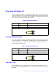
Dirty Cache LED Header (J1)
J1 is an optional two-pin header for connecting an LED to indicate a write command is
pending. This LED is known as the Write Pending LED. Use this LED with the write-back
cache feature. The dirty cache signal is driven by GPIO(5) of the LSISAS2208. The table
below shows how to connect an LED to the J1 header.
Table 3. Dirty Cache Header J1
Activity LED Header (J4)
J4 is a two-pin header for connecting an LED to indicate drive activity. This activity signal
is a logical combination of the GPIO(16) and GPIO(20) pins on the LSISAS2208 device.
Activity on either port causes the activity LED to turn on. The table below shows how to
connect an LED to the J4 header.
Table 4. Activity LED Header (J4)
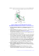
Heartbeat LED
The CR3 LED is mounted on the surface of the controller board. This LED is Green in
color and it indicates the LSISAS2208 device is alive. See Figure 8 for the location of the
CR3 LED.
Pin # Name Description
1 DIRTY_PU Anode of LED
2 DIRTY Cathode of LED
Illustration of how to connect the LED
Pin # Name Description
1 D_ACTIVE_PU Anode of LED
2 D_ACTIVE Cathode of LED
Illustration of how to connect the LED