Intel® RAID Smart Battery AXXRSBBU6 User’s Guide Order Number: E33722-001
Warranty Notice: Adding a battery on an Intel RAID controller will limit the warranty of this product. Returns determined to be caused by battery installation damage, stripped screws, or other damage resulting from the battery installation will not be covered. ESD damage to the board will also not be covered by the warranty. The warranty on the AXXRSBBU6 is 1 year. Disclaimer Information in this document is provided in connection with Intel® products.
Contents List of Figures..................................................................................................... iv List of Tables ...................................................................................................... iv About the Intel® RAID Smart Battery ...................................................................i Installing the AXXRSBBU6 ................................................................................. 3 Important Pre-installation Considerations ......
List of Figures Figure 1. Top and Bottom View of the AXXRSBBU6...................................................................3 Figure 2. Battery alignment on the add-in Intel® RAID Controllers ..............................................5 Figure 3. Battery board mounting on RAID controller board........................................................5 Figure 4. Reinserting an add-in RAID Controller .........................................................................6 Figure 5.
About the Intel® RAID Smart Battery Intel® RAID Controllers and Intel® Integrated Server RAID Modules provide reliability, high performance, and fault-tolerant disk subsystem management. A complete fault-tolerant strategy requires protection for all data, including the unwritten cached data in the RAM cache. If power is lost, the data in RAM is lost. To avoid this data loss, a battery can be added to supply power to the RAID RAM during an AC power outage or if the AC power cord is removed.
Important Safety Instructions Read all caution and safety statements in this document before performing any of the instructions. See Intel Server Boards and Server Chassis Safety Information at http://support.intel.com/support/motherboards/server/sb/cs-010770.htm. Wichtige Sicherheitshinweise Lesen Sie zunächst sämtliche Warn- und Sicherheitshinweise in diesem Dokument, bevor Sie eine der Anweisungen ausführen.
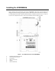
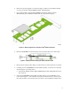
Installing the AXXRSBBU6 Figure 1 displays the top and bottom views of the AXXRSBBU6. The battery pack is mounted on a daughtercard which mounts to the RAID controller. Take note of the location of the J2 connector (5) which plugs into the Intel® RAID Controller and the 3 standoffs (2) and 6 screws (3). Only the top side of the daughtercard will be visible after installation onto the RAID controller. Figure 1. Top and Bottom View of the AXXRSBBU6 1. 2. 3. 4. 5. 6.
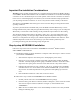
Important Pre-installation Considerations Warning: Always ground yourself and/or use a ground strap before touching the RAID controller or the RSBBU. Perform all installation work at an ESD-safe workstation. Use an ESD-safe Phillips screwdriver set to a maximum torque of 2.25 inch pounds, and be sure the screwdriver is centered in the screw to avoid damaging the screw head.
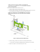
4. Remove the protective metal cover from the battery connector on the RAID controller card. (J10 on the Intel® SRCSASBB8I and Intel® SRCSASLS4I.) 5. On the Intel® RAID Controller SRCSASBB8I and the Intel® RAID Controller SRCSASLS4I, place the RAID controller with the components facing up. Figure 2. Battery alignment on the add-in Intel® RAID Controllers 6. Hold the AXXRSBBU6 so that the battery side is up and the three screw holes align. Figure 3. Battery board mounting on RAID controller board 7.
Caution: Center the screwdriver carefully to avoid stripping the screwhead. Do not over-tighten the screws. The maximum recommended torque is 2.25 inch pounds. C. Place the Intel® RAID Controller back into the server 1. Align the RAID controller with the PCI Express* slot. 2. Press down gently, but firmly, to ensure that the RAID controller is properly seated in the slot. The bottom edge of the RAID controller must be flush with the slot.
Monitoring Battery Backup Multiple utilities are available to display and configure BBU information including recharge count. When you replace a BBU, you should reset this counter to zero. Intel recommends that you replace the BBU once per year or after 500 recharge cycles, whichever comes first. Note: This chapter describes only the BBU-related features of the Intel utility programs. For complete information on these utilities, see the Intel® RAID Software User’s Guide.
Most of the Battery Module properties are view-only. In the lower right panel of the RAID BIOS Console there are two properties that can be changed. (Intel recommends that you leave these properties at their default settings.) • Learn Delay Interval – default 30 days • Auto Learn Mode – default Auto Note: The learning cycle is a battery calibration operation performed by the controller periodically to determine the condition of the battery.
• The current BBU temperature, voltage, current, and remaining capacity • The estimated time until the battery is fully charged (only if the battery is charging) Replacing Battery Backup Units Intel recommends that you replace BBUs once a year or after 500 recharging cycles, whichever comes first. The warranty on the battery pack is for one year. After you install a new BBU, use one of the Intel configuration utilities to reset the battery recharge cycle counter to zero.
Battery Backup Unit Specifications Table 1. Battery Backup Unit Specifications Battery Technology LiON (Lithium ION) 1 cell Battery Operating Environment 10–45°C ambient temperature 20% to 80% humidity non-condensing Battery Storage Temperature Depends on storage time,:< 30 days: 0–50 °C 30–90 days: 0–40 °C ‘; > 90 days: 0–30 °C Fast Charge Current 500mAH using charge circuitry card Battery Voltage Nominal OCV: 3.7 V Mechanical 2.611 inches x 2.