
Service Guide


Hardware Installations and Upgrades
Intel
®
Server System P4000IP and Intel
®
Workstation System P4000CR Service Guide 81
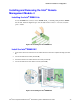
Installing an Additional Hot-swap Power Supply
Module
/
NOTE
This install procedure only applies to a chassis with redundant power supply capability.
WARNING
Hazardous voltage, current, and energy levels are present inside the power supply. There are no
user-serviceable parts inside it; servicing should be done by technically qualified personnel.
1. Observe the safety and ESD precautions at the beginning of this book.
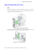
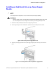
2. Insert finger into finger hole in middle of filler panel and remove the filler panel from chassis.
Figure 109. Removing Power Supply Filler Panel
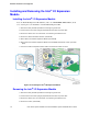
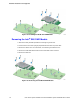
3. Insert the power supply module into the power supply cage and push all the way until it clicks into
place.
Figure 110. Installing Additional Hot-swap Power Supply Module