
Service Guide


Hardware Installations and Upgrades
64 Intel
®
Server System P4000IP and Intel
®
Workstation System P4000CR Service Guide
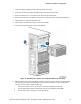
iv. Connect an I
2
C cable to the I
2
C _OUT connector of the bottom backplane and the I
2
C _IN connector
of the top backplane (see letter D).
Figure 79. Three 8x2.5” Hot Swap Backplane Cable Connections
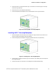
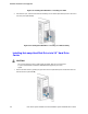
9. Install the front bezel. For instructions, see “Installing the Front Bezel (Pedestal Only)”.
10. Install the air duct if the air duct is removed. For instructions, see the Quick Start User’s Guide or Service
Guide provided with your Intel
®
server/workstation board.
11. Install the chassis cover. For instructions, see “Installing the Chassis Cover”.
12. Plug all peripheral devices and the AC power cable into the server.
13. Power up the server.
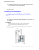
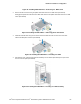
Removing and Installing 8x2.5” Hot-swap Backplane
Removing 8x2.5” Hot-swap Backplane
1. Observe the safety and ESD precautions at the beginning of this book.
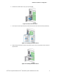
2. Power down the server and unplug all peripheral devices and the AC power cable.
3. Remove the chassis cover. For instructions, see “Removing the Chassis Cover”.
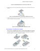
4. Remove the front bezel if it is installed. For instructions, see “Removing the Front Bezel (Pedestal
Only)”.