
Service Guide

Hardware Installations and Upgrades
Intel
®
Server System P4000IP and Intel
®
Workstation System P4000CR Service Guide 61
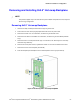
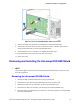
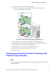
iii. Connect power cable to the power connector (see letter C).
iv. Connect an I
2
C cable to the I
2
C _OUT connector of the bottom backplane and the I
2
C _IN
connector of the top backplane (see letter D).
Figure 76. Two 8x2.5” Hot Swap Backplane Cable Connections
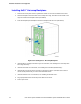
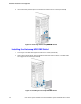
7. Install the front bezel. For instructions, see “Installing the Front Bezel (Pedestal Only)”.
8. Install the air duct if the air duct is removed. For instructions, see the Quick Start User’s Guide or
Service Guide provided with your Intel
®
server/workstation board.
9. Install the chassis cover. For instructions, see “Installing the Chassis Cover”.
10. Plug all peripheral devices and the AC power cable into the server.
11. Power up the server.
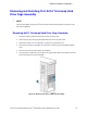
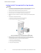
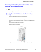
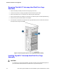
Removing and Installing Third 8x2.5” Hot-swap Hard
Disk Drive Cage Assembly
/
NOTE
This procedure applies only to the Intel
®
Server System P4000IP family with 8x2.5” hot-swap hard disk
drive cage configuration.