
Service Guide


Server Chassis Features
14 Intel
®
Server System P4000IP and Intel
®
Workstation System P4000CR Service Guide
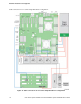
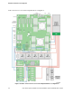
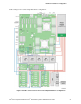
I. Opening for SPDIF cable
J. Padlock loop
K. RMM4 knockout
L. Front panel
M. CPU zone system fan(fan 2)
N. 5.25” peripheral bays
O. Air duck
P. PCI zone system fan(fan 1)
Q. Fixed Hard driver carrier tray
R. PCI card retainer
Figure 12. Internal Chassis View of Intel
®
Workstation System P4304CR2LFKN
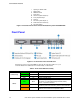
Front Panel
Figure 13. Front Panel Controls and Indicators
Descriptions of the front panel LEDs are listed in the following table. See your
server/workstation documentation for functionality of the buttons.
Table 6. Front Panel LED Functionality
LED
Color
Condition
What It Means
Power/Sleep
Green
On
Power on or S0 sleep.
Green
Blink
S1 sleep or S3 standby only for workstation baseboards.
Off
Off (also sleep S4/S5 modes).
Status
Green
On
System ready/No alarm.
Green Blink
System ready, but degraded: redundancy lost such as PS or
fan failure; non-critical temp/voltage threshold; battery
failure; or predictive PS failure.
Amber On
Critical alarm: Voltage, thermal, or power fault; CPU missing;
insufficient power unit redundancy resource offset asserted.
Amber Blink
Non-Critical failure: Critical temp/voltage threshold; VDR hot
asserted; min number fans not present or failed.