
Document

17
Software
• BIOS, Drivers, and Operating System Installation
A. Confirm BIOS Version: Look on the Server/System Management screen in the BIOS
Setup Utility to determine the installed BIOS version. Compare this to the versions at:
http://www.intel.com/support/motherboards/server.
If new versions are available, update the BIOS on your server. See the Techinical Product Specification
on the Intel
®
Server Deployment Toolkit CD for update instructions.
B. Configure your RAID Controller:
Use the instructions provided with the RAID controller.
C. Install your Operating System:
Use the instructions provided with the RAID controller
and with the operating system.
D. Install Operating System Drivers: With the operating system running, insert the
Intel
®
Server Deployment Toolkit CD. If using a Microsoft Windows* operating system, the Intel
®
Deployment Assistant will autorun and allow you to select the appropriate drivers to install. On other
operating systems, browse the CD folders to locate and install the driver files.
Side 2
9
Install Optical
Drive and
Hard Drive(s)
See the documentation that came
with your server chassis for drive
installation.
15
Install Add-in
Card[s]
For the Intel
®
Server System
P4000 series, see the Quick
Installation User's Guide
accompanying the chassis.
See the documentation that
came with your server
chassis for add-in card
installation.
16
Finishing Up
CAUTION: See your
chassis documentation
for AC power and
grounding requirements.
Before installing your operating
system, you must finish your
chassis installation, make I/O
connections and plug in AC
power.
See your chassis documentation
for AC power and grounding
requirements.
Intel® Workstation Board W2600CR Intel® Server Board S2600IP
NIC1
10/100/
1000 Mb
NIC2
10/100/
1000 Mb
NIC3
10/100/
1000 Mb
NIC4
10/100/
1000 Mb
Video
Serial A USB 2.0
0-1
USB 2.0
2-3
Network
NIC1
10/100/
1000 Mb
Audio
Back
Surround
out
Audio
Front
Surround
out
Audio
Side
Surround
out
Audio
Center/LFE
out
Audio
Microphone
in
Audio
Line-in
NIC2
10/100/
1000 Mb
USB 2.0
0-1
USB 3.0
0-1
USB 2.0
2-3
Network
Server
Board
Server
Board
Intrusion
Switch
Connector
12
Attach Intrusion Switch Cable
NOTE: For a non-Intel chassis, see your chassis documentation for
intrusion switch requirements.
IMPORTANT NOTE:
Return to your Intel
®
Server
System Quick Installation
User's Guide, or your
non-Intel chassis
documentation to finish
installation and
configuration of your Intel
®
Server Board S2600IP or
Intel
®
Workstation Board
W2600CR.
Return to this document to
finish up, including software,
BIOS, drivers and operating
system installation.
Internal
USB/Serial
Connector
Detail
Serial B
USB
Front Panel
USB
USB
Connector
Detail
13
Attach Front Panel, Serial, and USB Connections
NOTE: For a non-Intel chassis,
see your chassis documentation
for front panel features and server
board connection requirements.
C1DIMM C2 D1 D2
B2DIMM B1 A2 A1
E1DIMM E2 F1 F2
H2DIMM H1 G2 G1
Install DIMM Memory Modules ... continued
To Install DIMMs:
Open both DIMM socket levers.
Push down firmly on the DIMM until it
snaps into place and both levers close.
Insert DIMM making sure the connector edge
of the DIMM aligns correctly with the slot.
C
A
D
IMPORTANT! Visually check that each
latch is fully closed and correctly
engaged with each DIMM edge slot.
E
Note location of alignment notch.
B
CAUTION: Avoid touching contacts when
handling or installing DIMMs.
Memory Configurations and Population Order:
A
C
D
B
E
NOTE: For additional memory
configurations, see the Techinical
Product Specification for Intel
®
Server
Board S2600IP or Intel
®
Workstation
Board W2600CR at:
http://www.intel.com/support/mother
boards/server.
Memory sizing and configuration is
supported only for qualified DIMMs
approved by Intel. For a list of
supported memory, see the tested
memory list at
http://serverconfigurator.intel.com/def
ault.aspx
Memory Type: Minimum of one 1
GB, DDR3 800/1066/1333/1600 MHz
ECC UDIMM/RDIMM/LRDIMM.
Main Power
Connector Detail
C
Latch
Tab
CPU Power
Connector Detail
B
A
8
Make Server Board Power Connections
Attach the CPU 1 power connector.
Attach the CPU 2 power connector.
CAUTION:
Note the location of the
latch on each power cable
connector and align it with the matching
tab on each server board socket.
A
B
Attach the main power connector.
C
IMPORTANT NOTE:
If you are using a
non-Intel server chassis with an ATX
power supply, see the documentation
that came with your chassis for
installation information.
SATA Data
Cable Connector
Server
Board
SATA 0
SATA 1
MINI SAS_A
(Port 0-3)
MINI SAS_B
(Port 4-7)
MINI SAS Data
Cable Connector
11
Connect Hard Drives/Optical
Drive to Server Board
Connect SAS/SATA Data Cables to server board here.
NOTE: SATA/SAS functionality on ports 0-7 requires purchase of an
optional Intel
®
RAID C600 Upgrade Key, Please refer to RAID Quick
reference guide (G46033-003 ) in package for list of optional keys.
System Fan 1-6
Connector
Detail
System Fan 7
Connector
Detail
14
Chassis Fan Connections
For a non-Intel server chassis, see the documentation accompanying your chassis for specific chassis
fan connection requirements. Refer to the "Making Connections to the Server Board - Quick Reference"
section below.
Common Problems and Solutions
The system does not boot or show video at power-on.
•
Check that the +12V CPU power connector is plugged in. Without this cable, the processors will not have any power.
•
Intel
®
Xeon
®
Processor E5-2600 series
with 135 W and less Thermal Design Power (TDP) are supported on
Intel
®
Server Board S2600IP.
•
Intel
®
Xeon
®
Processor E5-2600 series
with 150 W and less Thermal Design Power (TDP) are supported on
Intel
®
Workstation Board W2600CR
.
•
Previous generation Intel
®
Xeon
®
processors are not supported.
•
Beep code 1-5-2-1 in a system means you do not have Intel
®
Xeon
®
Processor E5-2600 series
installed.
•
The system generates the memory error beep code and POST diagnostic LED message {0XE0~0XEF} that indicates memory errors in early POST .
•
Remember, all DIMMs must be:
–
DDR3 800/1066/1333/1600 MHz UDIMM/RDIMM/LRDIMM.
–
From the same manufacturer.
–
Installed beginning with DIMM A1.
For a list of hardware components that have been tested with
this system, see:
http://www.intel.com/support/motherboards/server.
Front Panel
C
MINI SAS
V
SATA
U
4Pin Power
W
Front Panel USB
X
HDD LED
S
eUSB SSD
AA
Chassis Intrusion
Z
Front Audio
AG
1394B
AD
Type A USB
AE
ROC Module
AC
Internal Video
M
HSBP_I
2
C
P
Serial B
O
IPMB
T
CPU 2 Power
A
CPU 1 Power
A
Main Power
B
CPU 2 Fan
L
CPU 1 Fan
K
DIMM E1
DIMM E2
DIMM F1
DIMM F2
DIMM C1
DIMM C2
DIMM D1
DIMM D2
DIMM H2
DIMM H1
DIMM G2
DIMM G1
DIMM B2
DIMM B1
DIMM A2
DIMM A1
Sys Fan 1
D
Sys Fan 2
E
Sys Fan 3
F
Sys Fan 4
G
Sys Fan 5
H
Sys Fan 6
I
S/PDIF
R
LCP
Y
TPM
AB
Storage Upgrade Key
Q
I/O Module
N
Sys Fan 7
J
RMM4 Lite
AF
RMM4 NIC
AH
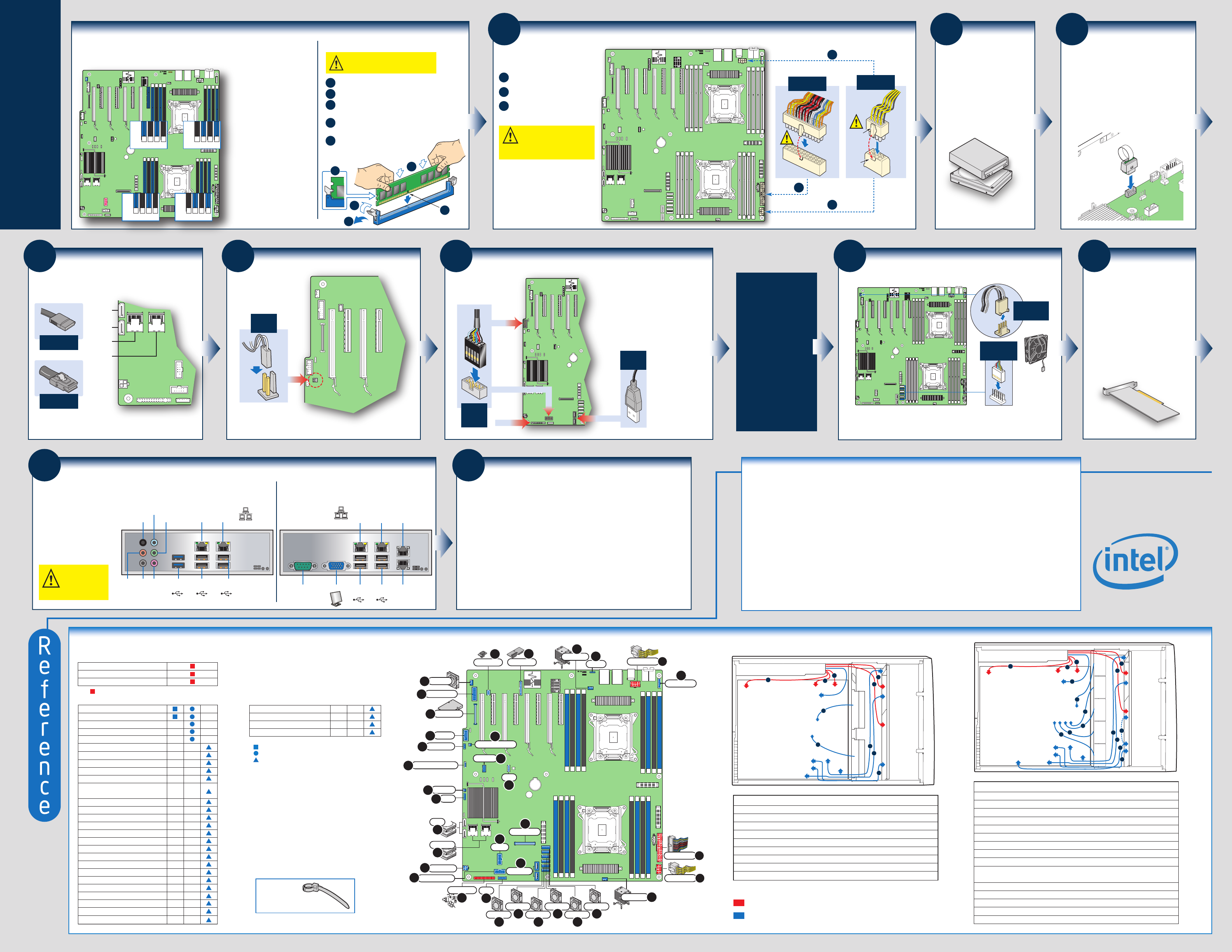
RED indicates power cable routing
BLUE indicates data cable routing
A. CPU1/CPU2 Power Cable
B. Server Board Main Power Cable
C. Fixed HDD Power Cable
D. ODD Power Cable
E. Front Panel Cable, USB Cable
F. ODD Data Cable (Connect To White SATA 6G Connectors On Server Board)
G. Fixed HDD Data Cable
H. System FAN 1
I. System FAN 2
Description
A. CPU1/CPU2 Power Cable
B. Server Board Main Power Cable
C. Backplane Power Cable
D. ODD Power Cable
E. Front Panel Cable, USB Cable
F. ODD Data Cable (Connect To White SATA 6G Connectors On Server Board)
G. MiniSAS (with SGPIO) Cable
H. PMBus Cable
I. HSBP_I
2
C Cable (From Server Board To First Backplane)
J. HSBP_I
2
C Cable (From First Backplane To Second Backplane when Second
Backplane Available)
K. System FAN 1
L. System FAN 2
M. System FAN 3
N. System FAN 4
O. System FAN 5
Description
FAN_3
FAN_2
FAN_1
FAN_4
FAN_5
Server Board
Power Supply
CPU2
CPU1
Main Power
Front
Panel
SAS/SATA
ODD
SAS/SATA
HSBP_I
2
C
USB
PMBus
B
A
A
D
C
I
J
G
E
F
K
L
N
M
O
H
FAN_2
FAN_1
Server Board
Power Supply
CPU2
Main Power
Front
Panel
SAS/SATA
ODD
SAS/SATA
USB
PMBus
CPU1
B
A
A
D
C
G
E
F
H
I
Cable Routing Diagram
Making Connections to the Server Board — Quick Reference
= Make this connection
Intel
®
Server Chassis
P4000 series
A. CPU 1-2 Power Connector
B. Main Power Connector
C. Front Panel Header
Required Connections
Intel
®
Server Chassis
P4000 series
Optional Connections
D. System Fan 1 Header
E. System Fan 2 Header
F. System Fan 3 Header
G. System Fan 4 Header
H. System Fan 5 Header
I. System Fan 6 Header
J. System Fan 7 Header
K. CPU 1 Fan Header
L. CPU 2 Fan Header
M. Internal Video (W2600CR only)
N. I/O Module (Not available for
S2600IP4L and W2600CR2L)
O. Serial B
P. HSBP_I
2
C
Q. Storage Upgrade Key
R. S/PDIF (W2600CR only)
T. IPMB
S. HDD LED
U. SATA Connectors
V. MINI SAS Connectors
W. 4Pin Power
X. Front Panel USB
Y. LCP
Z. Chassis Intrusion
AA. eUSB SSD
AB. TPM
AC. ROC Module
AD. 1394B (W2600CR only)
IMPORTANT NOTE:
Cables should be
tied for better airflow.
Use cable-ties compulsorily.
NOTE: For a non-Intel Chassis, see
your chassis documentation for server
board connection information.
NOTE: Not all optional connections are
shown in this diagram. Refer to your
Server Board Service Guide, and your
server chassis documentation for
additional connection information.
=
Make this connection to P4000L Workstation System
=
Make this connection to P4000L Server System
=
Make this connection when applicable
AE. Type A USB
AF. RMM4 Lite
AH. RMM4 NIC
AG. Front Audio (W2600CR only)
STOR_UPG_KEY
Match the Key and connector orientation and press
down to install.
10
Install Intel® RAID
C600 Upgrade Key
(Optional)