
Technical Product Specification

Intel® Server System R2000IP Product Family TPS Front Control Panel and I/O Panel Overview
Revision 1.1
55
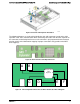
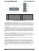
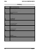
Label
Description
Label
Description
A
System ID Button w/Integrated LED
F
System Status LED
B
NMI Button (recessed, tool required for use)
G
Power/Sleep Button w/Integrated LED
C
NIC-1 Activity LED
H
Hard Drive Activity LED
D
NIC-3 Activity LED
I
NIC-4 Activity LED
E
System Cold Reset Button
J
NIC-2 Activity LED
Figure 45. Front Control Panel Features
A – System ID Button w/Integrated LED – Toggles the integrated ID LED and the Blue server
board ID LED on and off. The System ID LED is used to identify the system for maintenance
when installed in a rack of similar server systems. The System ID LED can also be toggled on
and off remotely using the IPMI “Chassis Identify” command which will cause the LED to blink
for 15 seconds.
B – NMI Button – When the NMI button is pressed, it puts the server in a halt state and issues
a non-maskable interrupt (NMI). This can be useful when performing diagnostics for a given
issue where a memory download is necessary to help determine the cause of the problem. To
prevent an inadvertent system halt, the actual NMI button is located behind the Front Control
Panel faceplate where it is only accessible with the use of a small tipped tool like a pin or paper
clip.
C, D, I and J – Network Activity LEDs – The Front Control Panel includes an activity LED
indicator for each on-board Network Interface Controller (NIC). When a network link is detected,
the LED will turn on solid. The LED will blink once network activity occurs at a rate that is
consistent with the amount of network activity that is occurring.
E – System Cold Reset Button – When pressed, this button will reboot and re-initialize the
system.
F – System Status LED – The System Status LED is a bi-color (Green/Amber) indicator that
shows the current health of the server system. The system provides two locations for this
feature; one is located on the Front Control Panel, the other is located on the back edge of the
server board, viewable from the back of the system. Both LEDs are tied together and will show
the same state. The System Status LED states are driven by the on-board platform
management sub-system. The following table provides a description of each supported LED
state.