
Technical Product Specification

Intel® Server System R2000IP Product Family TPS Power Subsystem
Revision 1.1
17
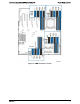
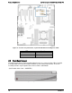
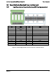
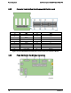
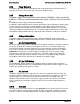
Connector
No. of pins
Description
P1
24
Motherboard Main Power Connector
P2
8
CPU1 Power Connector
P3
8
CPU2 Power Connector
P4
5
PMBus* Connector
P5
4
Motherboard 2x2 12V power connector
P6
6
HSBP power connector
P7
4
Peripherals Power connector (CD, SSDs)
Figure 19. Power Distribution Board Output Connectors
3.2.3.1 Power Distribution Board Connectors Pin definition
Table 4. P1 Baseboard Power Connector (P1)
Pin
Signal
Pin
Signal
1
+3.3VDC
13
+3.3VDC
2
+3.3VDC
14
-12VDC
3
COM
15
COM
4
+5VDC
16
PSON#
5
COM
17
COM
6
+5VDC
18
COM
7
COM
19
COM
8
PWR OK
20
Reserved
9
5 VSB
21
+5VDC
10
+12V1
22
+5VDC
11
+12V1
23
+5VDC
12
+3.3VDC
24
COM
Table 5. Processor Power Connectors (P2, P3)
Pin
Signal
18 AWG color
Pin
Signal
18 AWG Color
1
COM
Black
5
+12V1
Yellow
2
COM
Black
6
+12V1
Yellow
3
COM
Black
7
+12V1
Yellow
4
COM
Black
8
+12V1
Yellow
Table 6. PMBus* (P4)
Pin
Signal
24 AWG Color
1
I2C Clock
White
2
I2C Data
Yellow
3
SMBAlert#
Red
4
COM
Black
5
3.3RS
Orange