
Technical Product Specification

Intel® Server System P4000IP and Intel® Workstation System P4000CR Family TPS System Power Sub-system
72 Intel order number G38159-002 Revision 1.2
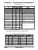
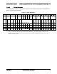
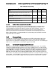
2.4.2.6 Hard Drive 12V rail configuration options
The below table shows the hard drive configuration options using the defined power
connectors. In some cases additional converter or ‘Y’ cables are needed.
Table 82. Hard Drive 12V rail configuration options
P8
P9
P10
P11
P5
P6
P7
1x4
1x4
1x4
1x4
1x5
1x5
1x4
18
3 x 2.5'' 8xHDD
BP
HDD1
8 x 2.5
na
HDD2
8 x 2.5
na
na
na
HDD3
8 x 2.5
2 x 3.5'' 4xHDD
BP
HDD1
4x3.5
HDD1
4x3.5
peripheral bay
1 x 3.5'' 8xHDD
BP
HDD1
8x3.5
na
na
peripheral bay
8 x 3.5'' fixed
SATA
2xfixed
2xfixed
2xfixed
2xfixed
peripheral bay
8 x 3.5'' fixed
SAS
2xfixed
2xfixed
2xfixed
2xfixed
peripheral bay
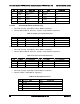
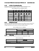
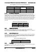
2.4.2.7 DC/DC Converters Loading
The following table defines power and current ratings of three DC/DC converters located on the
PDB, each powered from +12V rail. The 3 converters meet both static and dynamic voltage
regulation requirements for the minimum and maximum loading conditions.
Table 83. DC/DC Converters Load Ratings
+12VDC Input DC/DC
Converters
+3.3V Converter
+5V Converter
-12V Converter
MAX Load
25A
15A
0.5A
MIN Static/Dynamic Load
0A
0A
0A
Max Output Power
3.3V x25A =82.5W
5V x15A =75W
12V x0.5A =6W
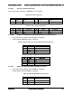
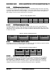
2.4.2.8 5VSB Loading
There is also one DC/DC converter that converts the 12V standby into 5V standby.
Table 84. 5VSB Loading
12V stby/5V stby
DC/DC Converters
MAX Load
8A
MIN Static/Dynamic Load
0.1
Max Output Power
5V x8A =40W