
Technical Product Specification

Intel® Server System P4000IP and Intel® Workstation System P4000CR Family TPS System Power Sub-system
70 Intel order number G38159-002 Revision 1.2
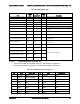
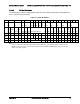
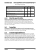
Pin
Signal
18 AWG Color
4
COM
Black
5
+12V3
Yellow
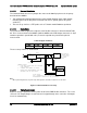
2.4.2.3 Grounding
The ground of the pins of the PDB output connectors provides the power return path. The
output connector ground pins is connected to safety ground (PDB enclosure). This grounding is
well designed to ensure passing the max allowed Common Mode Noise levels.
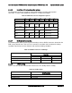
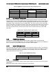
2.4.2.4 Remote Sense
Below is listed the remote sense requirements and connection points for all the converters on
the PDB and the main 12V output of the power supply.
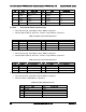
Table 79. Remote Sense Connection Points
Converter
+ sense location
- sense location
Power supply main 12V
On PDB
On PDB
12V/3.3V
P20 (1x5 signal connector)
P20 (1x5 signal connector)
12V/5V
On PDB
On PDB
12V/-12V
none
none
12Vstby/5Vstby
none
none
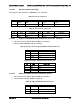
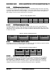
Table 80. Remote Sense Requirements
Characteristic
Requirement
+3.3V remote sense input
impedance
200 (measure from +3.3V on P1 2x12 connector to +3.3V sense
on P20 1x5 signal connector)
+3.3V remote sense drop
200mV (remote sense must be able to regulate out 200mV drop
on the +3.3V and return path; from the 2x12 connector to the
remote sense points)
Max remote sense current draw
< 5mA